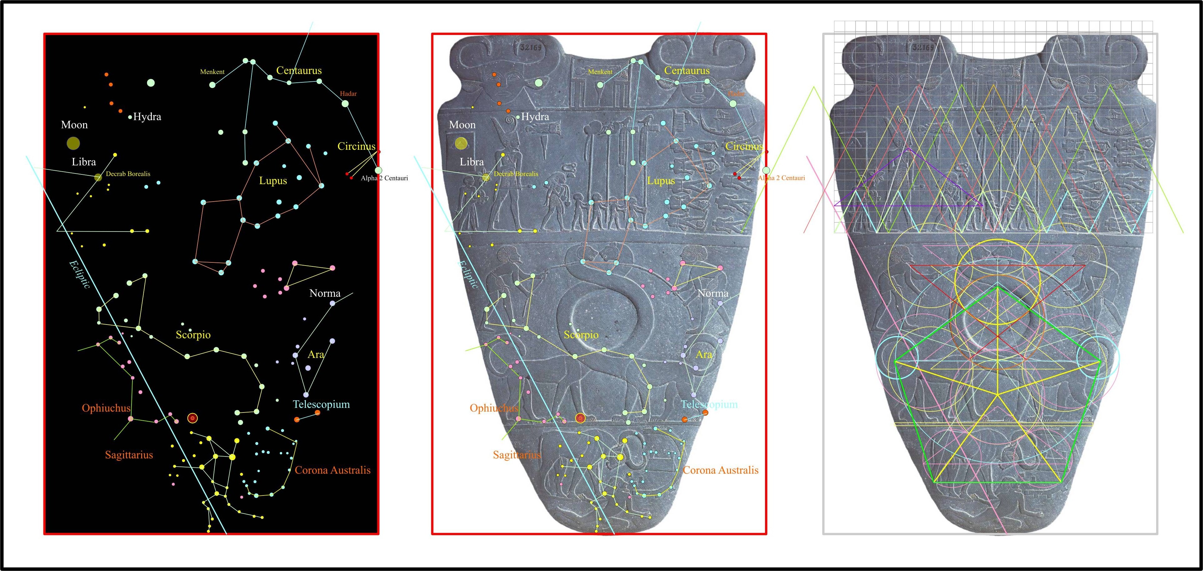
Back in 2008 I was studying many types of ancient artefacts and the relevance to star charts that do not appear on the walls or objects from ancient Egypt and was intrigued to find very little to say the least. After much research I later wrote an article “The Hidden Star Charts of the Ancients”, where I found the Narmer palette and some Sumerian seals had hidden star maps within the graphic design, I included it in my last Volume but left out the other side of the Narmer palette.
Here is the file that I didn’t include, I have also included a simple composite of the first side as well, which I had elucidated with much more details in my first volume. The details included the pictorial relevance to actual stars, galaxies and nebulae as they visually appear by modern powerful telescopes, an amazing revelation of this work. Regards Arto.
Below is the original side I studied.
Below is the Other Side.
If you want to read my original documents from 2011, Scribed has a copy you can down load, I have updated in 2013, here is the earlier version here:
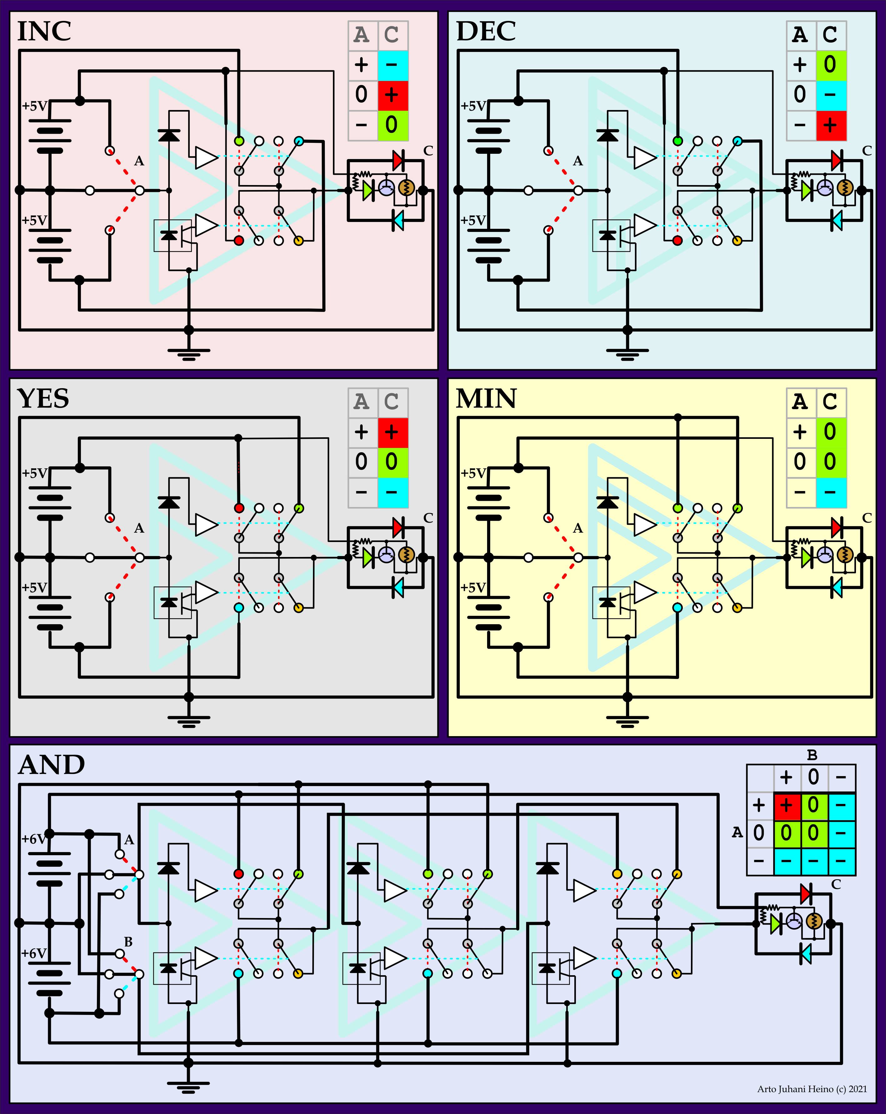
Rather than try to instigate the trinary action directly from the positive, neutral and negative charges, I have simplified it by setting the switches using only the positive rail and neutral before I have set the Unary Gates, using a ADG5236 Analog switch chip. This is only a testing measure to get all the gates ready for integration into combinatory sets like Tand and Tnor. You can say combinatory only in Ternary because each two input gate is made up of three Unary gates from a pool of 27, while each Unary gates is made up of three switched sets, sometimes as two pairs of DPDT while one is redundant, due to the lack of physical trinary switches available on the market.
I have tried not to compromise on either side of the switched in/out design, still we need to move these ideas forward so we can find interesting and valuable Ternary circuits that can accomplish much and more of what its little Binary brother has done in the last 80 years. The use of CMOS, PMOS, NMOS have been used successfully by many inventors to create Trinary circuits but have never been popularised due to the logical tangle of the unknown element “0”. This by philosophical terms is the “unknown”, “undefined” or “undecided” element, as binary has either Yes or No to which there is an easy determinate path to follow, no questions about a vague unknown.
This dilemma of the neutral place where indecision is its home, is merely an illusion that has been created by a physiological inability of our mind to see it any other way. I offer a simpler approach where S. C. Kleene, Post, Lukasiewicz and others has written much on the mathematics and semantics of this, where as I see it as a natural condition of our physical universe. The Earth is the simple model I follow, where the positive charges are above us and the negative charges are below us, while we stand on the neutral ground. This simple model also works for water and any other boundary situation where “0” is now the path of all connections made by its very nature, a skin if you like. (as above a mirror as it is below). Indecision is not unknown, it can be weighed just as gravity can be defined by units being weighed, a heavy object as opposed to a light one.
Much has been written about mathematics of ternary and it has its advantages over binary for sure, here is some simple arithmetic. Again I follow my simple model:
There is a simple and enduring beauty using trinary logistics, you never end up in a lock up situation, due to the neutral line where it can always carry its logic to a complete solution. The binary has the problem of only having a “true” and “false” narrative, where that is not how nature works at all.
The early Atomic physicists had to resort to phantoms of matter such as “Electrons”, “Neutrons” and “Protons”, these are mere conventions of usage not a reality of our universe. They used these mnemonic devices to solve abstractions they did not fully comprehend. Charge is all we really know, sadly the Ether was incorrectly dismissed in the 20th Century as the carrier of all the physical universe, not so, as we should simply state that charge is one of the different conditions of the Ether. This also makes the Ether as a neutral state, thus making it the default condition of everything that is not moving, or charged in any way, while Gravity is the Pressure of the Ether on all Mass.
Once Trinary thought is used in all circumstances, War, Famine, Invention and Mans ailing conditions will improve beyond mere Utopian dreams. False narratives and political agendas will be nothing but illusions we will all see through and will serve no purpose in our pursuit of our quality of life and living. The Us and Them syndrome are but Marxist drivel used to divide our sensibilities against the true knowledge of our existence.
Trinary thinking no longer separates us into “Right” and “Wrong”, “True” and False”, “Yes” and “No” but introduces gradations of wisdom and experience. I ask is it wrong that a bird can walk while it is only known to fly in the minds of many. Is the colour of the sky Blue when we see it as Red, Orange and Yellow at other times. Binary thinking divides our perceptions along a boundary, this boundary is the “Undecided” or Neutral line which we will now understand in Trinary thought, as the connector of everything. In electrical engineering it has always been called “Earth”, “Common” or “Neutral”.
Art precedes science just as culture precedes politics, this is why “reductio ad absurdum” of modern philosophy is a regressive step with the binary decision trees built from notions of “Left” and “Right” factions are nonsense and are a danger to our own survival. The Quantum arguments currently exploited by “Modern Science” are but Binary semantics made into a religion, called “Scientism”. The rulers of our lives only require serfs not thinking individuals, who have, graduations of thought and experience where true diversity only exists when we are allowed to think freely.
Addition of Trinary
+ add + = +-
which is
1 + 1 = 2
+- add +- = ++
which is
2 + 2 = 4
so if “-” = -1
then
– add – = -+
which is
-1 + -1 = -2
Try
-1 + 1 = 0 or 1 – 1 = 0
which is
– add + = 0
So a balanced ternary system is similar to the way we use electrical charge as well.
Here are the diagrams from my work, it will be included in my next volume “Talking To The Birds, Volume II”, coming soon, regards Arto.
The last two post were my personal dialog with Trinary procedures so I can start to create complex decision trees that can act in a intelligent and logical way. These are the beginnings into a natural engineered form of intelligence, I dare not say AI as these ideas are not artificial, they are natural only non living.
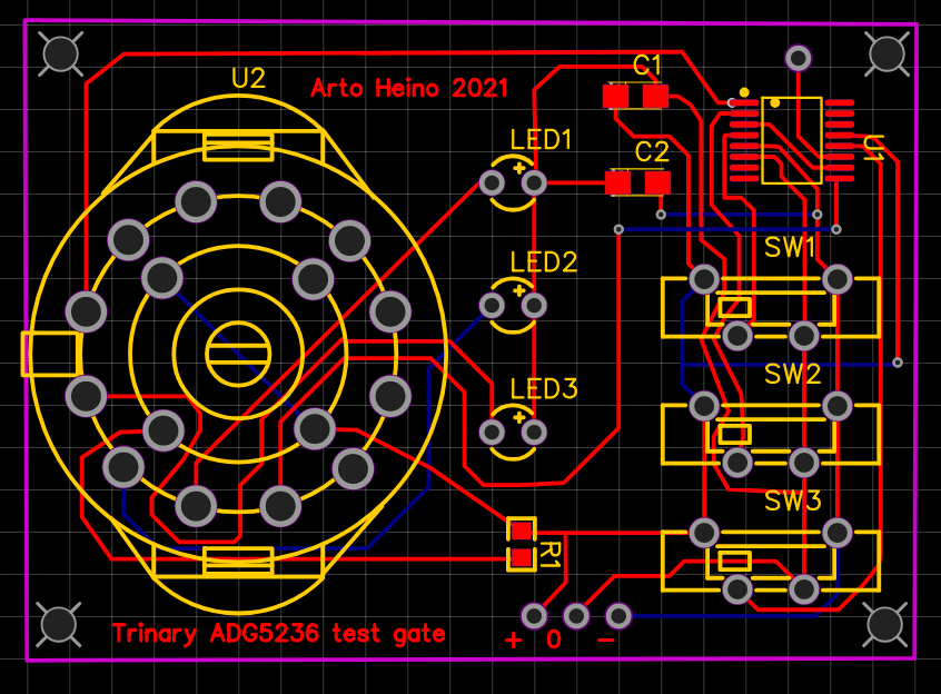
I went back to some of my work with the DG series of chips so I could make an interface board for the Led Matrix. I could design it with relays but decided that it would be great to see other options for Trinary design. Once mastered, an ALU would be the first step, maybe with many extra functions that binary ALU’s struggle to implement. I hope to add a Trinary version of Quantum Arithmetic built from these gates. (Not Quantum Mechanics)
The first hurdle to climb is to test the DG403.
The next is to define the Trinary gates required.
Then create a schematic and a PCB board
Here is the DG403 version of an TAND gate
****Warning**** everything here has not been tested, so I apologise for any errors.
I hope you enjoy my adventure, it has been a long, quite, happy and while being a lonely journey, it is never boring, excitement for the future is beyond any reward, regards Arto.
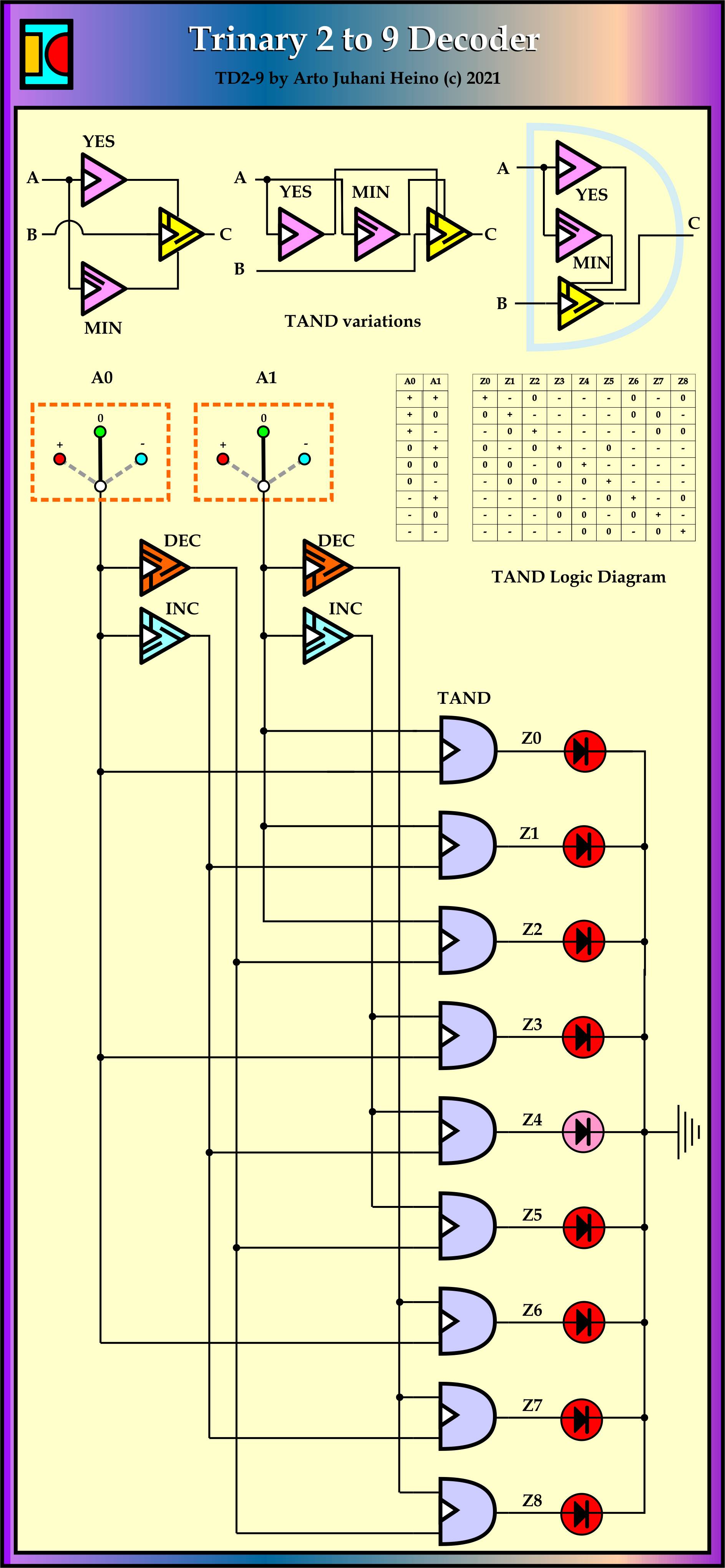
The completion of the trinary understanding in relays has been very rewarding, this is my first attempt at a trinary decoder chip version of the 3-8 decider 74138, where a 2-9 decoder TD2-9 is a trinary designed device that would also do the job. It could be fabricated with FETs and miniaturised so it fits onto existing chip boards.
As I see this as my first step into making useful and efficient circuitry based on trinary inputs and easily adapted to the standards in current use. I see great promise in adapting trinary systems to current binary as a step into integration. These ideas are adaptable and flexible to be used in some AI systems. even now.
The long dreamed idea of a trinary system was to advance understanding of natures logic and repair the mistakes made in the service of short gain which is full of hubris and greed. Current digital systems can be 256 wide, but not in most cases they run 64bit and 32bit subsystems even some 16 and 8 bit are in the mix, is all due to the through put required by graphic chips to reduce time lags and memory bottle necks with all that constraint issues.
These behemoth super computer systems are complex to design and control. let us look some maths.
Binary Trinary
0………+ 0 – 2 bit…….3 trit 4 bit…….9 trit 8 bit…….27 trit 16 bit…..81 trit 32 bit…..243 trit at this point we have reached beyond our current systems 64 bit…..729 trit 128 bit…2187 trit 256 bit…6561 trit 512 bit…19683 trit As you can see that 64bit computing is the norm at present and moving into 128bit at lighting pace. Where we could have reached 729 trit in the same time frame. imagine the 64bit super cellphone you hold in your hand would have been the norm in 1980’s. This is the amount of development retardation we were forced to endure due to short sightedness and unripe understanding of all the future issues at hand. This simple list shows one aspect, here the binary decoder version
So a 3 to 8 decoder has the trinary equivent of the 2 to 9 decoder, if we ueed 3 inputs we would arrive at 27 outputs, the advantages are simple.
Trinary Inputs and Trinary outputs Trinary Inputs and Binary outputs Binary Inputs and Binary outputs Binary Inputs and Trinary outputs 1___3……..TD1-3 2___9……..TD2-9 can also act like two of 4 bit dual level logic (2 Only gates make a Sure gate) 3___27……TD3-27 4___81……TD4-81 5___243….TD5-243 6___729….TD6-729
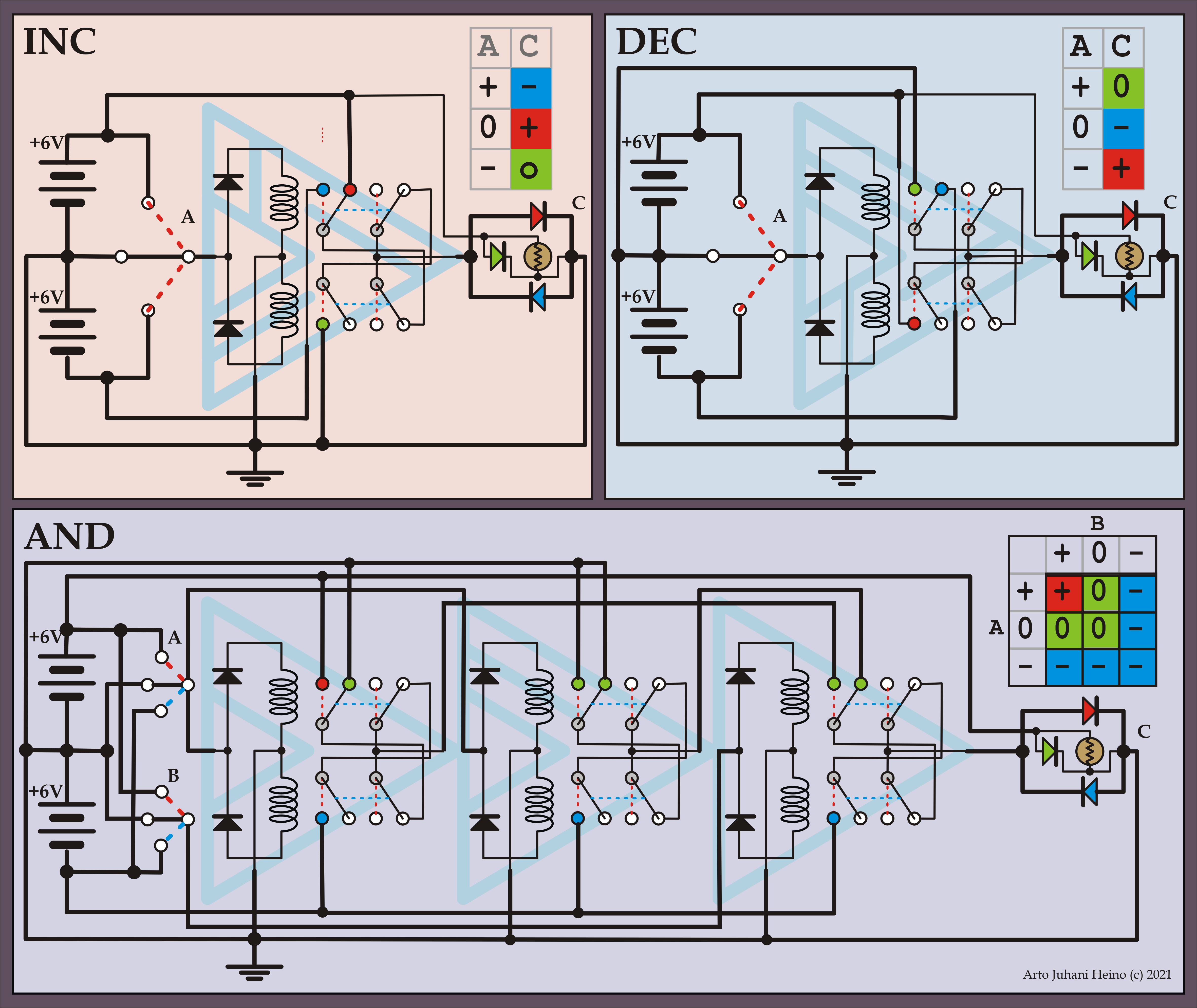
There are no off the shelf trinary chips to build useful devices from these decoders as yet.At this present form(very large relays) you could apply these trinary systems to AI of the grid system, where self regulation with the enviroment is required and not optional. As you are dealing with an Earth that has all three parts of the trinary logic, the Sky, the surface and Inner Earth, as ” + 0 – “. I have extended the understanding here to illustrate our well of energy we walk upon.
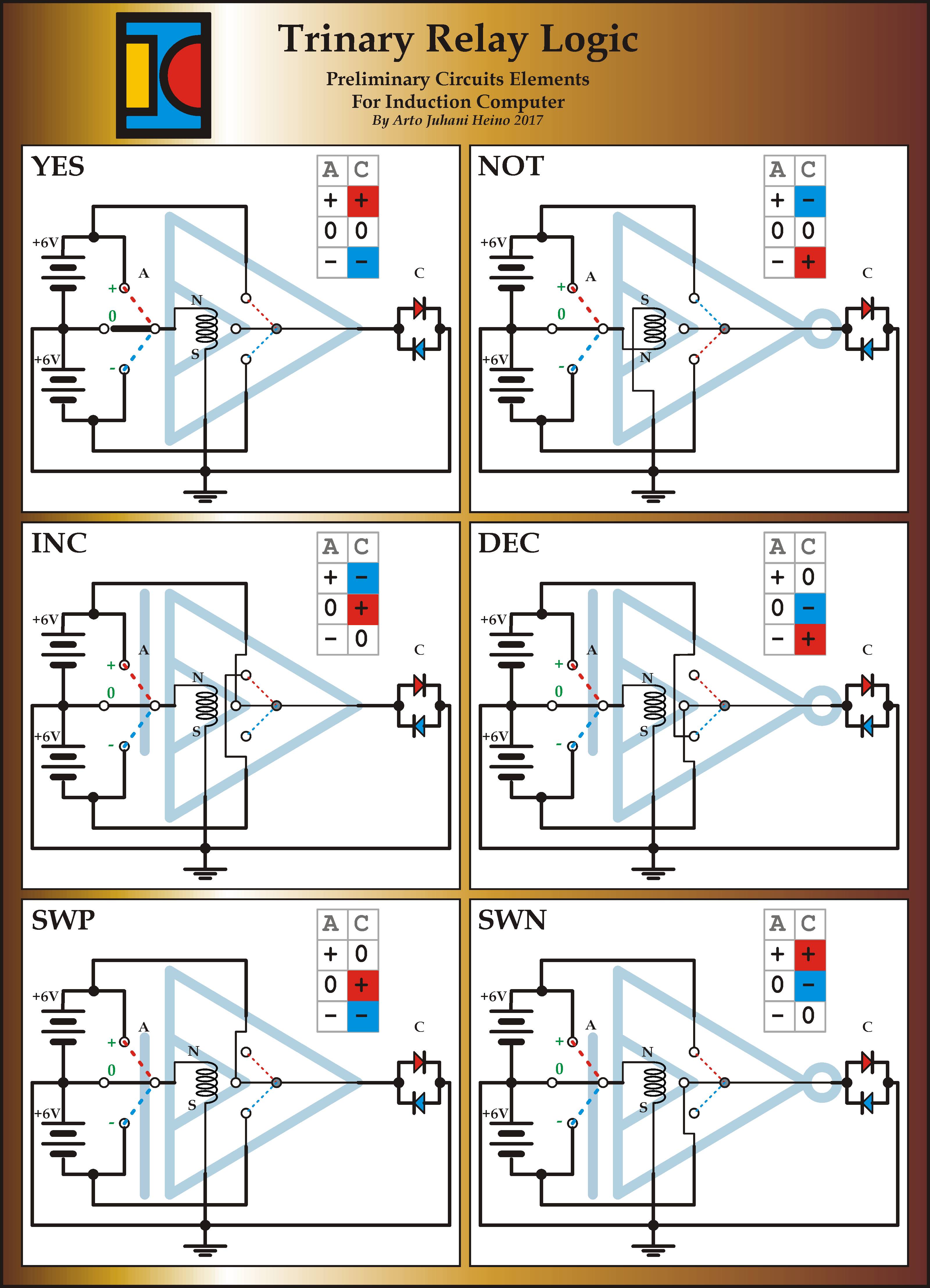
This diagram illustrates the relay design of the three different trinary gates you need here. You can make the relays a small or big as you need . Everything here is simple and easily built on you electronic bench, please feel free to use these gates in a project.
INC and DEC gates and a TAND gate
As now I have decided upon my choice of trinary AND gates, which there are a few, the TAND gates now lives amongst my circuit ideas. More decoders and encoder to be illustrated very soon.
TD2-9 Trinary Decoder
Here is the place this circuit will live, 2 of these to drive the 16 pin 8 x 8 led matrix (ADM-388C0). How simple is that, 4 trinary trits control 81 LED locations, 64 for the Matrix and 17 for other things.Regards Arto.
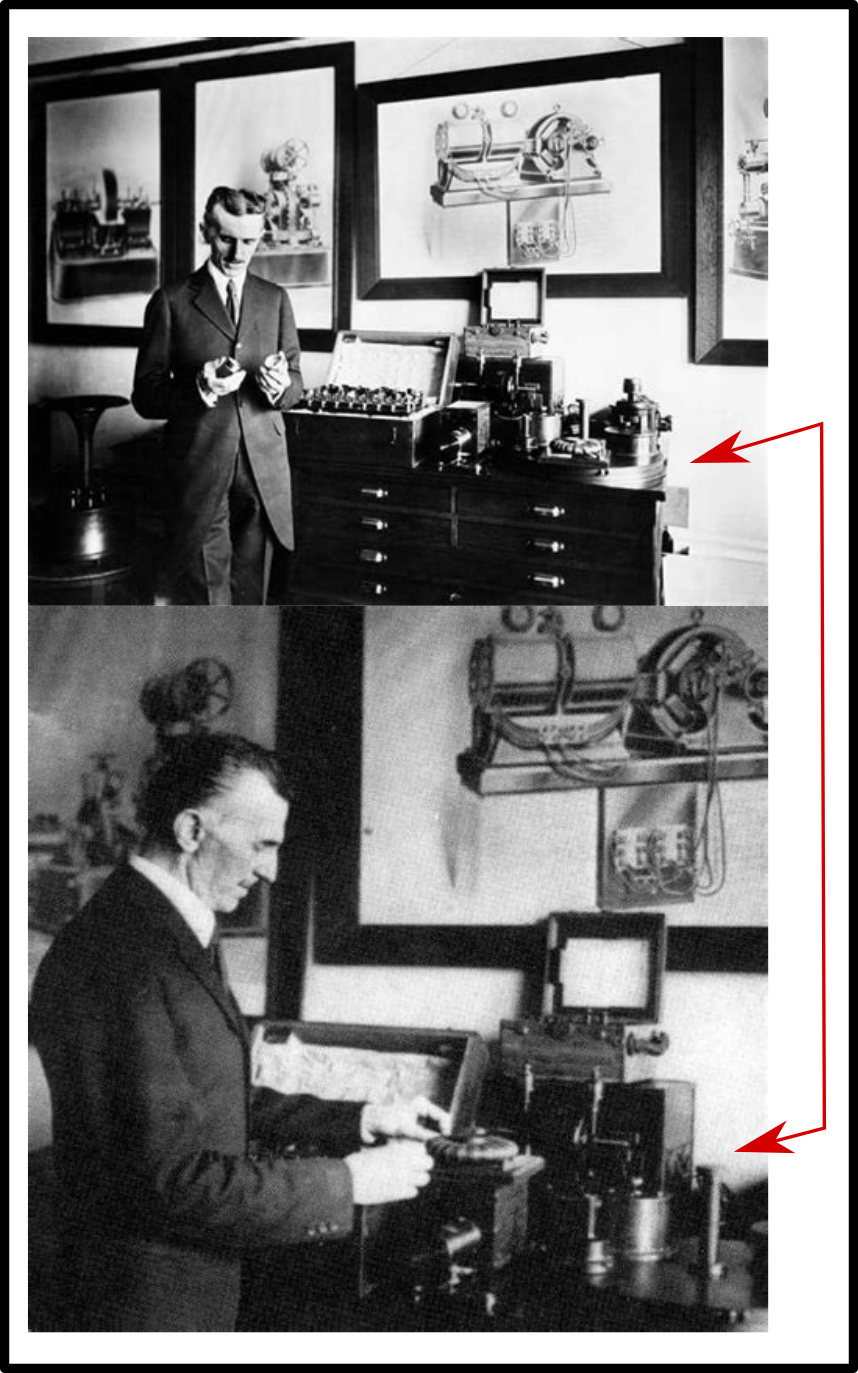
I forgot to add this vital understanding of volume and surface area regarding Tesla coils.
First you must realise that Tesla placed a high premium on getting the resonant factors correct. That any amount of electricity has a definite number (be coulombs or esu or ?) and must be included in the overall design structure. When the resonant action has been instigated there is a transference of magnetic to electrostatic potentials and visa versa, this must be balanced and carefully considered. The impedance matching is of vital importance to this action but a secondary balance is the volumes and areas of each set of coils.
The exact parameters can be calculated and you can see by Tesla’s work in Colorado Springs, he realised that a short cylindrical coil can be better utilised than a long coil and a flat spiral is much more compact than any cylinder can be. These studies had revealed to Tesla a beautiful geometric design that cannot be improved any further, a very compact and portable unit that awaits a audience that has chosen to ignore his proclamations. Below is the coil I am talking about.
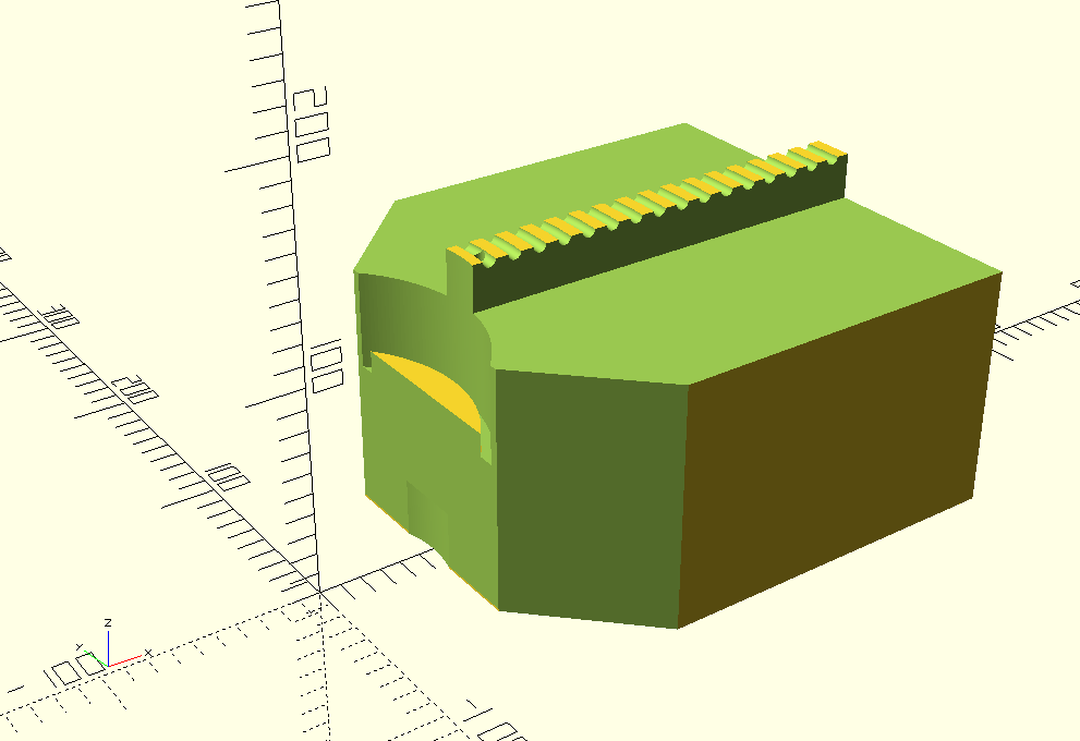
I have drawn up such a coil system, approx 400mm x 400mm x 200mm unit (approx), it unfolds and plugs into a power source (Tesla AC) and hopefully communicates to a clone at a preset short distance with losses. Not only voice/data but Energy as well (100 watts or so). The frequency was always too high to be of use in power transfer as the losses increased with the frequency.
Below are listed only my estimates by reading much data and personal experience.
Tesla system (no compromise).1 to 5…………………………..95 to 99
Radio system…………………………….99.9 to 100 0………………1 to 0.00001
High freq Tesla Flat……………………40……………………………….60
High freq Tesla Cyl……………………..60………………………………40
Low freq Tesla Flat…………………….15……………………………….85
Low freq Tesla Cyl……………………..30……………………………….70
So why did I design 336366 coil system using a traditional long cylinder? Simple, convenience and to prove to myself that the longitudinal velocity is the KEY to instant communication as Tesla suggested. Efficiency was not always the driving factor but the ease of material supply and a personal demand for longer wave lengths in a simple setup. The flat coil size became problematic in many ways, still I will go down that road again.
Coil…………………………………………………………..Volume and Area
Volume of Secondary………………………………0.0004 Cubic Mtrs
Surface Area of Secondary………………………0.796 Sqr Mtrs
MAX Volume of Primary…………………………..0.00068 Cubic Mtrs
MIN Volume of Primary……………………………0.000016 Cubic Mtrs
MAX Surface Area of Primary…………………..0.424 Sqr Mtrs
MIN Surface Area of Primary……………………0.01 Sqr Mtrs
Primary Volume at the design size…………..0.00045 Cubic Mtrs
Primary Surface Area at the design size…..0.285 Cubic Mtrs
What Turn…………………………………………………..14
What Area Secondary to Primary Equiv……..0.78 Sqr Mtrs
What Turn (beyond this design)…………………26
What Volume Secondary to Primary Equiv…0.0004 Cubic Mtrs
What Turn (very close )…………………………….13
I want to follow up with the real McCoy, in the not too distance future, regards Arto.
As this is part of my chapter on Tesla Coils, I might as well fill you in. I had recently consumed something that affected my stomach, not pleasant, it gave me an ulcer. So while I was recovering, with natural remedies, I decided try to finish one of my Tesla Coil designs.
I have been tentatively working on this Tesla Coil project for a few years(8 lol), specifically for Transmitting and Receiving, using 700 mtrs as a distance that needs to be crossed or a multiple of this, 1400, 2100, 2800 etc.
I figured that building from standard parts with a simple STL 3D prints with an accurate dimensional scheme we should get frequency matching accuracy due to the uniformity of the build.
Here is a TXT file, which is a couple of SCAD programs, that I have been translating my Tesla Coil Data to make a jig I can 3D print and put the main components of the Tesla Coil into a simple assemblage with some 3D parts.
1 x 1000mm of 110 tube 1 x 150/110 base connector 1 x 350 + mtrs of AWG 21 wire 1 x 16 mtrs of 1/4 copper tube 1 x 3Dcoil BaseL STL 1 x 3Dcoil BaseR STL 2 x 3Dcoil Base/edge Connector STL 1 x 100mm ball (Al, Cu) or (STL + Al foil) 1 x 4 point Switch Configuration Adapter STL 1 x 240v/15000v 60 ma Transformer 1 x Rotary Spark Gap 8″ dim + 12 protrusions at 400 RPM, makes 80 BPS 1 x Safety anti kick back system (protecting Mains & transformer)
Inductance of the Primary Coil will be from- 0.376 uH to 150.25 uH I tap mine at 14.17386 turns which gives me 67.846873 uH Capacitance for Primary Coil: 0.0033 uF Voltage across Cap (max 30000): 21210 volts Secondary DC resistance: 14.6647 Ohms
I chose:
Frequency = 336366.3513 hz 110 mm tube x 800 mm length of winding of secondary coil = 350 mtrs The wave Length of The Longitudinal wave is different to EM wave if WL = V1 / ( Lw x 4 ) = 1400 mtrs or WL = V2 / F1 = 1400 mtrs
Consider an explosion, the shock wave is the longitudinal wave and the matter with splintered bits and fire is the transverse wave. Electricity has the same properties.
I use these formulae:
Ls = Secondary Coil Inductance Lt = Secondary Coil Stray inductances + added adapter unit Lst = Total inductance of Secondary Coil Cs = Secondary Capacitance of Coil Ct = Top Capacitance + stray Caps Cst = Total Capacitance of Secondary Coil
Lp = Primary Coil Inductance Lq = Primary Coil Stray inductances Lpq = Total Inductance of Primary Coil Cp = Primary Capacitance Cq = Stray Capacitances of coil + adjuster Cpq = Total Capacitance for the Primary coil
V1 = Electro Magnetic (Transverse Magnetic) Light Velocity (lagging) V1 = 299792456 V1 = (Lw / 0.52324)^3 approx V2 = Magneto Electric (Longitudinal Electrostatic) Velocity (leading) V2 = V1 x pi / 2 V2 = 470912891.8272 V2 = 900000000 x 1 royal cubit (0.52324 mtrs)
note the different phase relationships between Voltage(electrostatics) and Amperage(magnetics) when you consider Power.
The Electrostatic Velocity leads Electromagnetism by pi/2. The only reason resonance occurs is the exchange from inner volume electro-magnetics running at Light velocity to outer surface electrostatics running at pi/2 times this, which is still proportional to the same amount of Energy. But the velocity is out by pi/2, allowing the circuit to breath.
E = 1/2 x (Cpq x Vp^2) = 0.5 x (0.00330 uF x 0.000001) x (21210 volts)^2 E = 1/2 x (Lpq x Ip^2) = 0.5 x (67.8468 uH x 0.000001) x (147.917 amps)^2 E = 1/2 x (Cst x Vs^2) = 0.5 x (15.5688 pf x 0.00000000001) x (308785 volts)^2 E = 1/2 x (Lst x Is^2) = 0.5 x (0.01438 H) x (10.16 Amps)^2 E = 0,74222 Joules E = W * t
WL = Wave Length Lw = Wire Length (I use 350 mtrs)
F1 = 1 / ( 2 x pi x sqrt( Lst x Cst ) F2 = 1 / ( 2 x pi x sqrt( Lpq x Cpq ) F3 = V2 / WL F4 = (V1 / ( Lw x 4 )) x pi / 2 F5 = (V1 / WL ) x pi / 2 F6 = V2 / ( Lw x 4 )
Q = XL / R Q = 30000 / 15 My calculations show a secondary maximum Q of about 2000 Across my cap about 20000 volts Q x V = 40,000,000 volts
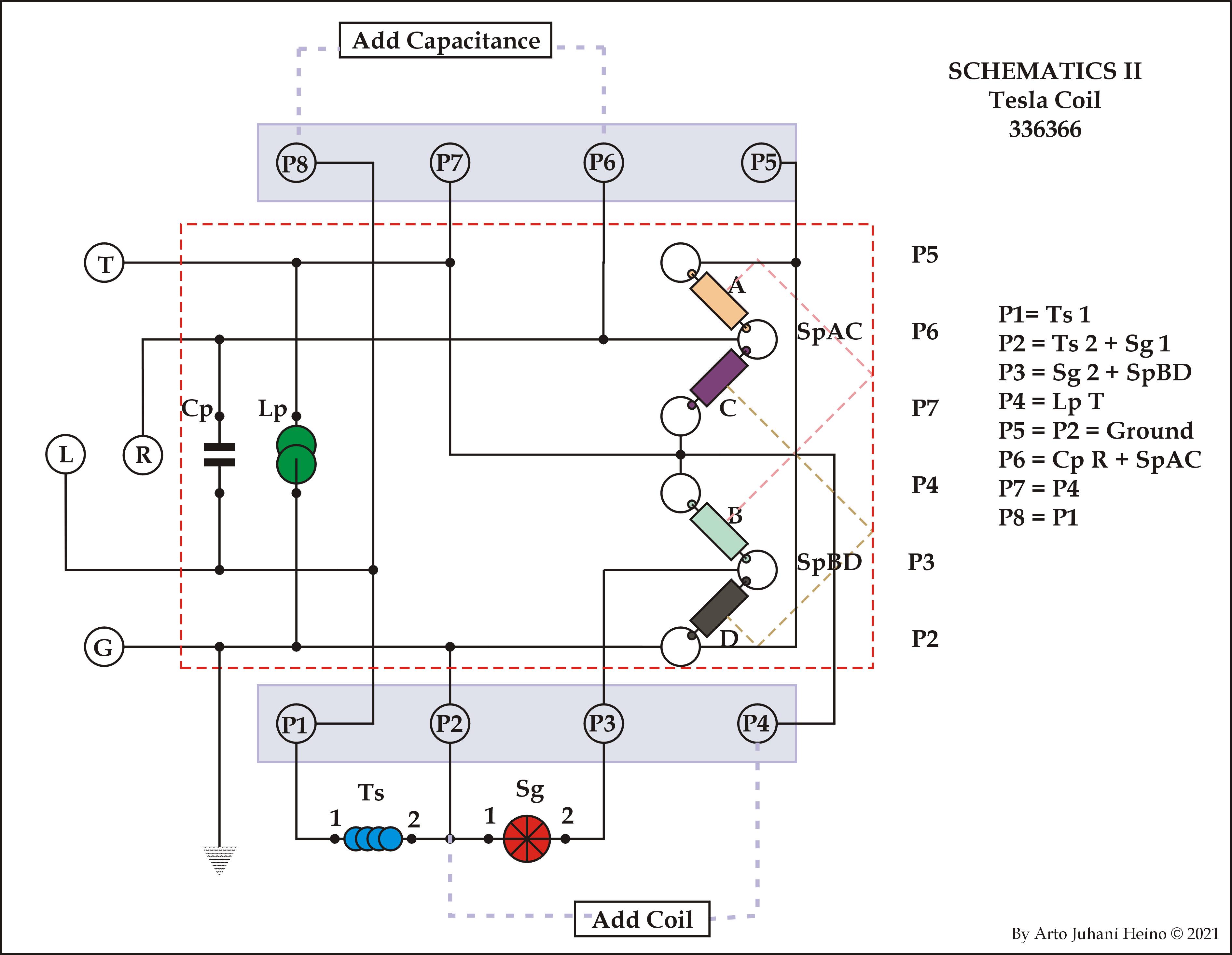
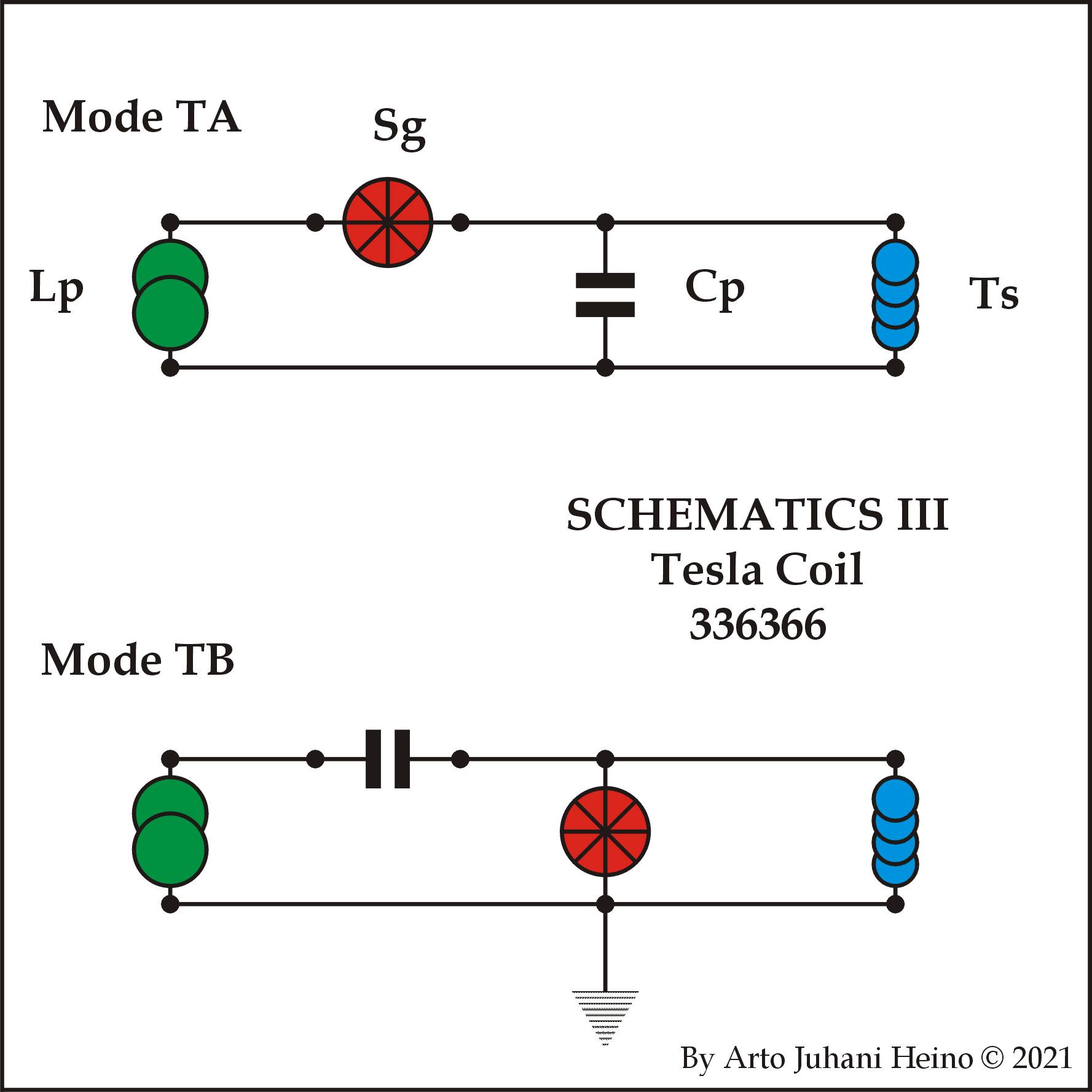
Diagrams
The way I envisaged to switch over the 2 base Tesla designs was to just plug a unit into the side of the Tesla Coil Structure and it would be a matter of pulling a lever of setting a key switch to run in either mode.
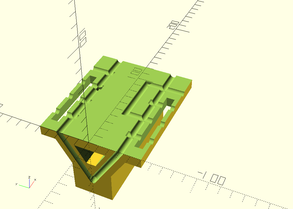
I incorporated the Capacitance cavities so you could add more later, as you see by the ports P8 and P6 are their for that reason. P2 and P4 are there if you need to reduce your inductance by any degree by paralleling another wound inductor on a metal former. These ports allow you to experiment and modify as needed.
The main point of the Adaper unit was to make it as simple as plugging your HV-Transformer and Spark Gap into a simple 1/4″ set of bolts. Follow the instructions and all will work as planned.
I have drawn three different schematics, so you can see the simple logic I used for expansion into the real world by geometric means. The design of the two triangles was so the inductance is reduced by it opposing parallels.
My Thoughts
This is only theoretical but clearly plausible if air break down is not an issue while only on on minimum idle, the loaded system when doing work will reduce safely to about 300,000 volts and less.
Next Stage
The next part of the project will be setting up a transceiver system that can exchange energy between two points 700 mtrs apart, also at 700 times the number of wave lengths, losses must be calculated by trial and error. I am guessing safely over rough terrain about 4.9 km with acceptable losses (note – grid harmonics).
Speculation
When needed, you can relay a transmission to further distances if the original signal degrades too far. You could possibly relay the Energy in Solar collectors that runs the Tesla coil and transmit it around the world, as the Earth spins, as the other relays they will start up the energy cycle again, then relay it to the next one. A continuous energy loop that is harnessing the Sun 24 hours a day. No wires, you would need 360 of these at 1 degree intervals, which is about 111 kms apart. This distance is no issue to a large well made Tesla Transmitter.
I hope you enjoy reading about this project I am still working on, regards Arto.
By the way here is the SCAD files, incomplete as yet, I will add it HERE later.
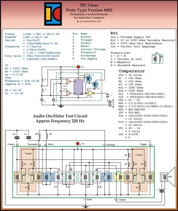
I am back from the wilderness, the experiences of Spring has overwhelmed my Audio and Visual organs, natures beauty is beyond any simple description. The last post I never mentioned the Trinary system that took my designs closer to a complete new type of thinking to develop a Trinary ALU, much more interesting than the Binary approach. Here is the 555 timer I promised from the last post, it is closer to a build-able relay design than my first prototype.
I didn’t show any parameters for the Basic Logic Cell. Here is my sizes and reasoning:
The Basic Logic Cell – Logical Unit
Working from the true measure the Royal Cubit approx 523.24mm, rounding to 525mm. The Palm is four fingers and seven palms make the Royal Cubit.
75mm x 75mm Sqr (aprox 3″ x 3 “)= 1 square Palm.
18.75mm Thick(rounding to 19mm, aprox 3/4” ) = 1 finger thick.
This was why I chose the Ancient Royal Cubit, when you measure the longitudinal velocity of light in royal cubits equals exactly 900000000. Thus it is the exact measure of the Royal Cubit.
Velocity of Light = C
= 299792458 mtrs sec
Longitudinal Velocity of Light = Pi/2 x C
= 1.5708 x 299792458
= 470912891.8272 = CL
Therefore
= CL/900000000
=470912891.8272/900000000
= 0.5232365 Mtrs
= 1 Royal Cubit
This means all your measures you use on materials is concordant to a universal standard, so by coordinating Electrical, Sonic and Hydraulic wave forms in your Logical Unit, all the impedance issues would be known, thus engineer-able.
The Universal Binary Engine
To complete my journey back to relays here is one draft of the Universal Binary Engine, it was designed to be used with a rotary commutator in mind, I was considering the technology of 1900 and the implementation of the Tesla tower as a the hub of computing the Longitudinal Ground Wave communication traffic he would have had to encounter if his tower was finished. Here are my preliminary data covering the commutator and/or relay computer. I have dubbed it “The Universal Binary Engine“, it has motoring logic built in, so a rotating system is viable, a whole new way of conveying intelligence through simple matrix connections with commutators , setting up codes for binary transmission in as many bits as needed. This would be similar to the type of computer switching system Tesla could have worked out during his Wardenclyff period, to direct the control of a complex communication system, with subscribers numbering into the hundreds of millions, not bad for pre-transistor or valve era. Each bit would be just another commutator in rows of switching array commutators, this way you can accommodate large address locations on the globe using a whole wave node number(Earth circumference wave number derived from the frequency of operation) and the directions NSEW as your location matrix. I have a vision in my mind regarding the operational frequencies and mechanical rotating frequencies to make such a system operate as a World Wireless System (NOT Radio), here is a draft PDF of one of my ideas. Here. As this was about laying the most simplest wiring and layout, where you could his own switching systems as per Patent 685953, as illustrated in my Volume I, page 343. I always draft my original designs by free hand sketches and hand written work books, while I am design the Trinary version as well this way, I only draw my work on computer long after I have cleared up any mistakes, either physically tested or carefully worked out on spread sheets.
Trinary
Here is list of the first 6 Trinary single input logic gate operations, there are more that I will list shortly.
The Switch is of great importance here, the three distinct actions are of a greater Logic to apply than just on and off. The beginning of a decision tree within the three way action, yes, maybe, no. Where most will see the “0” as a null action it is a vital internal pivot to allow a current flow in be diverted for other operations, as you will see in these basic two input relay gates.
The design scheme was very involved, looking at history and to develop a version that was simple and functional, as my earlier designs show we can still lose the battery and use magnets. The next few gates tested my underlying geometry as a square 5 internal layout.
I have completed the Or, Nor, Xor and Xnor gates and the many other possible logic gates have been noted and configured for future design steps.
The ideas for using the new found parameters available haven’t been explored in the main stream forums as yet, it is not so much the answers they can provide but what are the questions we need to ask and what solutions these gates can provide, we are looking for problems that need solving, this is what will propel these ideas forward. Here is the third page of the steps to arrive at a simple Trinary system with only batteries, switches and leds.
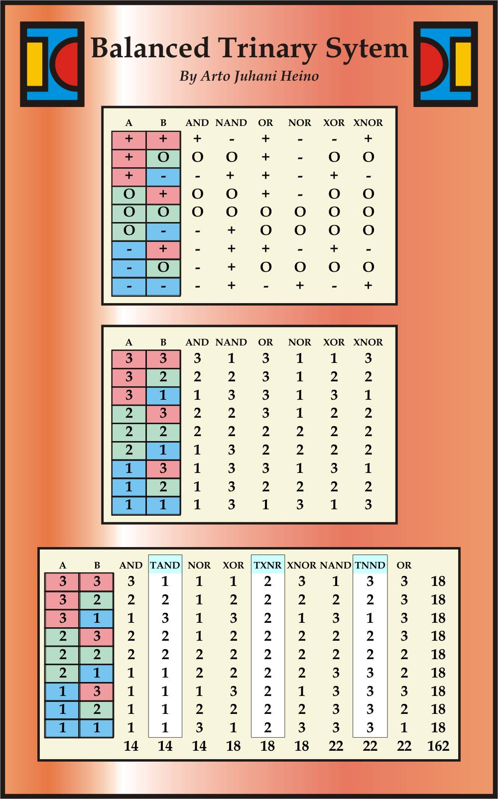
This table below shows some my more interesting breakdown of Logical Gates and new concepts of interaction with the extra three Logical operators to complete another Axiom to investigate.
(18×18)/2 = 162
162 approximates PHI
Thus in an abstracted manner, I am applying natural arithmetic, with a golden Ratio as its final Sum.
I am still working on these and will add another post soon, Regards Arto.
From my last entry I hinted at a 555 relay emulation, I am not quite their yet, I am getting close though. Here is my current stage I am on at the present moment.
I needed an ALU to start things of, so I started on the Half-Adder as a building block, here is my iterations.
The next step is the Full-Adder and its first few iterations from Logic Gates.
Lastly I have included a simple idea of how some of these could be interpreted in the 3D world, more to come on this aspect in a future blog.
If your response is high enough, I will start a Patreon account and begin building the real thing, regards Arto.
It looks like I am reinventing the wheel, minus valves and transistors, this work might even seem redundant to some of the techno-nerds. I assure you this is a step forward, there has been no time in the last 50 years that all those electronic enthusiasts have been able to simplify and create something without an official corporately designed IC package doing all your brain-work for you, leaving nothing for your own original imagination. I was very excited many years ago when many hobbyists made their own computers from discreet transistors and IC packages, while a few even made some relay ALUs.
While I thought of making my own CPU from relays but resisted, I first needed to create a new architecture that could incorporate an open 256 bit CPU and a Analog CPU in one package, while still accessible enough to be built by hand. This was part of my goal, as the architecture had to be robust, to last 1000 years, the components were to be the built environment and the power to drive it should be available 24/7, sounds like a pipe dream of some mad scientist. I only dare to dream of its reality and decided to rediscover the simplicity and the basic technology to make it plausible. The idea of using stone to contain the complex logical matrix that can be accessed via simple interfaces is the final reality, the many steps to arrive at that outcome might outstrip my lifetime, still I will persist, as I cannot dismiss a vision that is clear and within the realms of possibility.
Enough of my machinations, here are some interesting and practically solved devolutions of known devices from my last posting. Here is a FlipFlop made from two relay NAND gates.
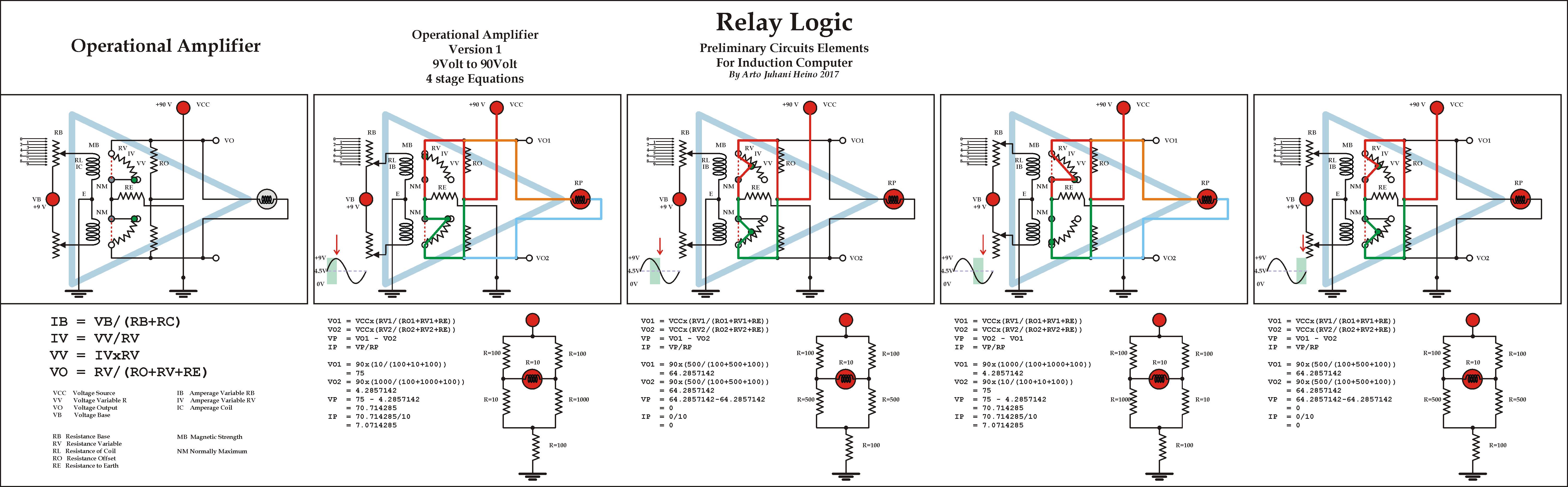
While the idea of a Operational Amplifier kept me awake for a night of two, I hope to emulate a 555 IC chip from my work here, just in time to compete a chapter in my Volume II.
This version should satisfy many of its Integrated Chip operations, still it is a crude and very fundamental design, useful to be expanded upon with a bit more work. I must repeat, I am not an electrical engineer and I have no degree from any University, I am truly a ground up natural scientist, where my tenets of understanding come from a life time of artistic creativity with careful observations and practical applications. I hope those who are interested can learn much from my ideas. Regards Arto.
Here are some interesting combinations using relays as logic gates, which was where I began this first step into the Induction Computer.
As you can see I have “single relays” and “double pole relays” and “Latch relays”, an old technology that goes back to the beginnings of the study of electromagnetism in the 1800’s. My studies into remnant magnetism of different materials, brought me into an understanding of natural rocks and the possibility of using either “Granite”, other rocks or even a poured casting as a magnetically imprinted “Logic Matrix Array”, storing functions, complex procedures, information and even pictures, videos and music.
In the Voltage Multiplier I have even eliminated any semiconductors, even diodes and batteries, while only using coils, capacitors, magnets and relay operations. You can see my process of elimination and the final schematic being without any high tech micro components.
There are a few parts to make the whole system function, here are some of the descriptions for the Voltage Multiplier.
The Slab that must have
1 Remnant Magnetism within permissible limits
2 Flat Surface, possibly engraved for descriptive and functional reasoning
3 Location keys for Imprinter and Reader
The Matrix Imprinter
1 Magnetic Array
2 Electromagnetic Array
3 Reset and Wipe function
The Induction Reader
1 Layered Switch Array
2 Geometric Coil Matrix
3 External Switches/Buttons and Levers/Handles arced or rotary
Physical Actions of Operator
1 Generate Voltage
2 Instigate Switch Operations
3 Discharge to external device
As this blog article is only to describe some of my work, it is not the whole article, that you will find in my next volume of “Talking To The Birds” Volume II. If the interest in these ideas are popular, I would consider a FundMe or Patreon profile and begin the arduous progress of a working system , regards Arto.
An error has occurred; the feed is probably down. Try again later.
Join 130 other subscribers
Published material Link
Talking to the Birds
Book Available NOW
At Amazon
At Createspace
https://www.createspace.com/4513692
______________________
Cartoons
http://www.scribd.com/doc/106684504/Scraps-Sketches-and-Satire
_______________________
Magic Square
http://www.scribd.com/doc/33050524/The-Magic-Square-of-Three-Crystal


