As this is part of my chapter on Tesla Coils, I might as well fill you in. I had recently consumed something that affected my stomach, not pleasant, it gave me an ulcer. So while I was recovering, with natural remedies, I decided try to finish one of my Tesla Coil designs.
I have been tentatively working on this Tesla Coil project for a few years(8 lol), specifically for Transmitting and Receiving, using 700 mtrs as a distance that needs to be crossed or a multiple of this, 1400, 2100, 2800 etc.
I figured that building from standard parts with a simple STL 3D prints with an accurate dimensional scheme we should get frequency matching accuracy due to the uniformity of the build.
Here is a TXT file, which is a couple of SCAD programs, that I have been translating my Tesla Coil Data to make a jig I can 3D print and put the main components of the Tesla Coil into a simple assemblage with some 3D parts.
1 x 1000mm of 110 tube
1 x 150/110 base connector
1 x 350 + mtrs of AWG 21 wire
1 x 16 mtrs of 1/4 copper tube
1 x 3Dcoil BaseL STL
1 x 3Dcoil BaseR STL
2 x 3Dcoil Base/edge Connector STL
1 x 100mm ball (Al, Cu) or (STL + Al foil)
1 x 4 point Switch Configuration Adapter STL
1 x 240v/15000v 60 ma Transformer
1 x Rotary Spark Gap 8″ dim + 12 protrusions at 400 RPM, makes 80 BPS
1 x Safety anti kick back system (protecting Mains & transformer)
Inductance of the Primary Coil will be from-
0.376 uH to 150.25 uH
I tap mine at 14.17386 turns which gives me
67.846873 uH
Capacitance for Primary Coil:
0.0033 uF
Voltage across Cap (max 30000):
21210 volts
Secondary DC resistance:
14.6647 Ohms
I chose:
Frequency = 336366.3513 hz
110 mm tube x 800 mm length of winding of secondary coil = 350 mtrs
The wave Length of The Longitudinal wave is different to EM wave
if
WL = V1 / ( Lw x 4 ) = 1400 mtrs
or
WL = V2 / F1 = 1400 mtrs
Consider an explosion, the shock wave is the longitudinal wave and the matter with splintered bits and fire is the transverse wave. Electricity has the same properties.
I use these formulae:
Ls = Secondary Coil Inductance
Lt = Secondary Coil Stray inductances + added adapter unit
Lst = Total inductance of Secondary Coil
Cs = Secondary Capacitance of Coil
Ct = Top Capacitance + stray Caps
Cst = Total Capacitance of Secondary Coil
Lp = Primary Coil Inductance
Lq = Primary Coil Stray inductances
Lpq = Total Inductance of Primary Coil
Cp = Primary Capacitance
Cq = Stray Capacitances of coil + adjuster
Cpq = Total Capacitance for the Primary coil
V1 = Electro Magnetic (Transverse Magnetic) Light Velocity (lagging)
V1 = 299792456
V1 = (Lw / 0.52324)^3 approx
V2 = Magneto Electric (Longitudinal Electrostatic) Velocity (leading)
V2 = V1 x pi / 2
V2 = 470912891.8272
V2 = 900000000 x 1 royal cubit (0.52324 mtrs)
- note the different phase relationships between Voltage(electrostatics) and Amperage(magnetics) when you consider Power.
- The Electrostatic Velocity leads Electromagnetism by pi/2. The only reason resonance occurs is the exchange from inner volume electro-magnetics running at Light velocity to outer surface electrostatics running at pi/2 times this, which is still proportional to the same amount of Energy. But the velocity is out by pi/2, allowing the circuit to breath.
E = 1/2 x (Cpq x Vp^2) = 0.5 x (0.00330 uF x 0.000001) x (21210 volts)^2
E = 1/2 x (Lpq x Ip^2) = 0.5 x (67.8468 uH x 0.000001) x (147.917 amps)^2
E = 1/2 x (Cst x Vs^2) = 0.5 x (15.5688 pf x 0.00000000001) x (308785 volts)^2
E = 1/2 x (Lst x Is^2) = 0.5 x (0.01438 H) x (10.16 Amps)^2
E = 0,74222 Joules
E = W * t
WL = Wave Length
Lw = Wire Length (I use 350 mtrs)
F1 = 1 / ( 2 x pi x sqrt( Lst x Cst )
F2 = 1 / ( 2 x pi x sqrt( Lpq x Cpq )
F3 = V2 / WL
F4 = (V1 / ( Lw x 4 )) x pi / 2
F5 = (V1 / WL ) x pi / 2
F6 = V2 / ( Lw x 4 )
WL = V2 / F1
V2 = V1 x pi / 2
Lst = Ls + Lt
Cst = Cs + Ct
Lpq = Lp + Lq
Cpq = Cp + Cq
These are the requirements
F1 = F2 = F3 = F4 = F5 = F6
and
WL = Lw x 4
and
Lst x Cst = Lpq x Cpq
Primary Coil Parametrics
Inductance per turn:
1 = 0.370488 uH
2 = 1.363580
3 = 2.918217
4 = 5.038095
5 = 7.750477
6 = 11.092889
7 = 15.107919
8 = 19.840884
9 = 25.338680
10 = 31.649171
11 = 38.820833
12` = 46.902557
13 = 55.943511
14 = 65.993060 14.17386 = 67.846855 uH
15 = 77.100714
16 = 89.316083
17 = 102.688860
18 = 117.268792
19 = 133.105676
20 = 150.249344
Q = XL / R
Q = 30000 / 15
My calculations show a secondary maximum Q of about 2000
Across my cap about 20000 volts
Q x V = 40,000,000 volts
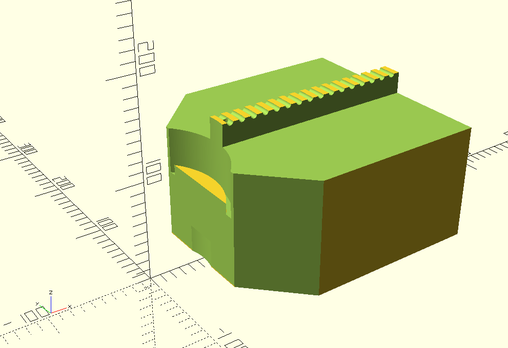
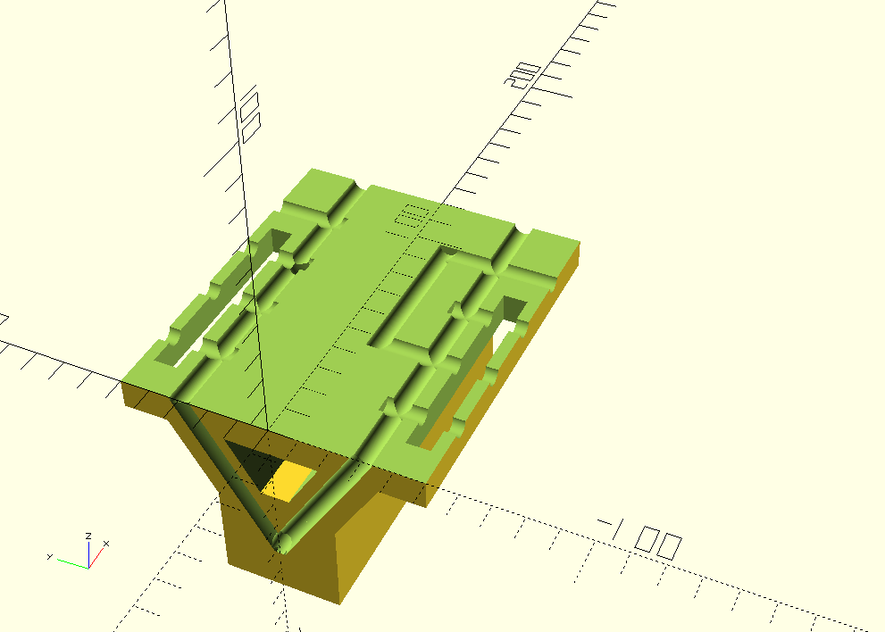
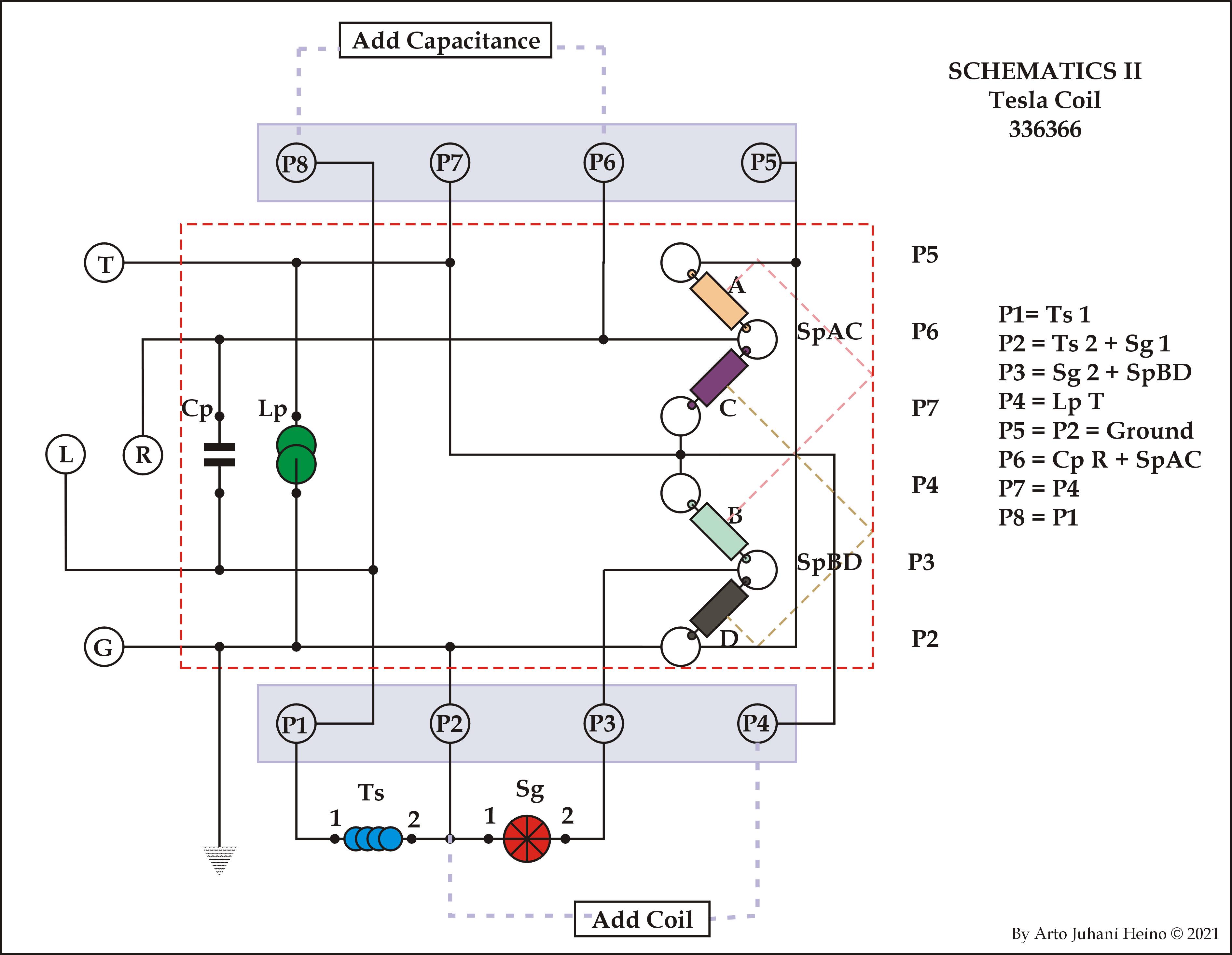
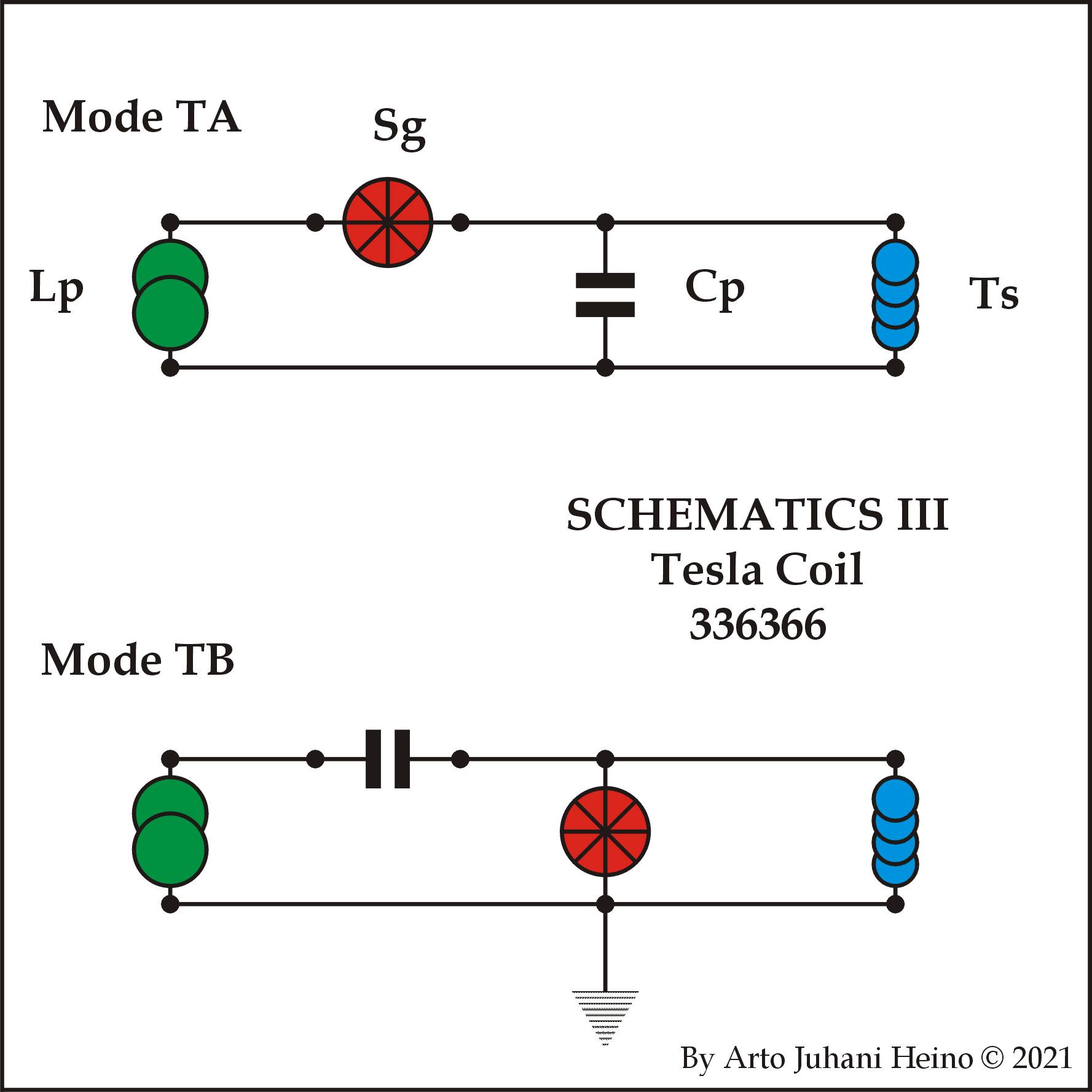
Diagrams
The way I envisaged to switch over the 2 base Tesla designs was to just plug a unit into the side of the Tesla Coil Structure and it would be a matter of pulling a lever of setting a key switch to run in either mode.
I incorporated the Capacitance cavities so you could add more later, as you see by the ports P8 and P6 are their for that reason. P2 and P4 are there if you need to reduce your inductance by any degree by paralleling another wound inductor on a metal former. These ports allow you to experiment and modify as needed.
The main point of the Adaper unit was to make it as simple as plugging your HV-Transformer and Spark Gap into a simple 1/4″ set of bolts. Follow the instructions and all will work as planned.
I have drawn three different schematics, so you can see the simple logic I used for expansion into the real world by geometric means. The design of the two triangles was so the inductance is reduced by it opposing parallels.
My Thoughts
This is only theoretical but clearly plausible if air break down is not an issue while only on on minimum idle, the loaded system when doing work will reduce safely to about 300,000 volts and less.
Next Stage
The next part of the project will be setting up a transceiver system that can exchange energy between two points 700 mtrs apart, also at 700 times the number of wave lengths, losses must be calculated by trial and error. I am guessing safely over rough terrain about 4.9 km with acceptable losses (note – grid harmonics).
Speculation
When needed, you can relay a transmission to further distances if the original signal degrades too far. You could possibly relay the Energy in Solar collectors that runs the Tesla coil and transmit it around the world, as the Earth spins, as the other relays they will start up the energy cycle again, then relay it to the next one. A continuous energy loop that is harnessing the Sun 24 hours a day. No wires, you would need 360 of these at 1 degree intervals, which is about 111 kms apart. This distance is no issue to a large well made Tesla Transmitter.
I hope you enjoy reading about this project I am still working on, regards Arto.
By the way here is the SCAD files, incomplete as yet, I will add it HERE later.