The Induction Computer Part 4
by Arto Juhani Heino (c) 2017
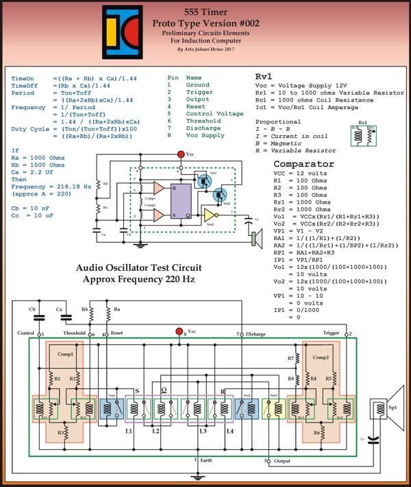
I am back from the wilderness, the experiences of Spring has overwhelmed my Audio and Visual organs, natures beauty is beyond any simple description. The last post I never mentioned the Trinary system that took my designs closer to a complete new type of thinking to develop a Trinary ALU, much more interesting than the Binary approach. Here is the 555 timer I promised from the last post, it is closer to a build-able relay design than my first prototype.
I didn’t show any parameters for the Basic Logic Cell. Here is my sizes and reasoning:
The Basic Logic Cell – Logical Unit
Working from the true measure the Royal Cubit approx 523.24mm, rounding to 525mm. The Palm is four fingers and seven palms make the Royal Cubit.
75mm x 75mm Sqr (aprox 3″ x 3 “)= 1 square Palm.
18.75mm Thick(rounding to 19mm, aprox 3/4” ) = 1 finger thick.
This was why I chose the Ancient Royal Cubit, when you measure the longitudinal velocity of light in royal cubits equals exactly 900000000. Thus it is the exact measure of the Royal Cubit.
Velocity of Light = C
= 299792458 mtrs sec
Longitudinal Velocity of Light = Pi/2 x C
= 1.5708 x 299792458
= 470912891.8272 = CL
Therefore
= CL/900000000
=470912891.8272/900000000
= 0.5232365 Mtrs
= 1 Royal Cubit
This means all your measures you use on materials is concordant to a universal standard, so by coordinating Electrical, Sonic and Hydraulic wave forms in your Logical Unit, all the impedance issues would be known, thus engineer-able.
The Universal Binary Engine
To complete my journey back to relays here is one draft of the Universal Binary Engine, it was designed to be used with a rotary commutator in mind, I was considering the technology of 1900 and the implementation of the Tesla tower as a the hub of computing the Longitudinal Ground Wave communication traffic he would have had to encounter if his tower was finished. Here are my preliminary data covering the commutator and/or relay computer. I have dubbed it “The Universal Binary Engine“, it has motoring logic built in, so a rotating system is viable, a whole new way of conveying intelligence through simple matrix connections with commutators , setting up codes for binary transmission in as many bits as needed. This would be similar to the type of computer switching system Tesla could have worked out during his Wardenclyff period, to direct the control of a complex communication system, with subscribers numbering into the hundreds of millions, not bad for pre-transistor or valve era. Each bit would be just another commutator in rows of switching array commutators, this way you can accommodate large address locations on the globe using a whole wave node number(Earth circumference wave number derived from the frequency of operation) and the directions NSEW as your location matrix. I have a vision in my mind regarding the operational frequencies and mechanical rotating frequencies to make such a system operate as a World Wireless System (NOT Radio), here is a draft PDF of one of my ideas. Here. As this was about laying the most simplest wiring and layout, where you could his own switching systems as per Patent 685953, as illustrated in my Volume I, page 343. I always draft my original designs by free hand sketches and hand written work books, while I am design the Trinary version as well this way, I only draw my work on computer long after I have cleared up any mistakes, either physically tested or carefully worked out on spread sheets.

Trinary
Here is list of the first 6 Trinary single input logic gate operations, there are more that I will list shortly.
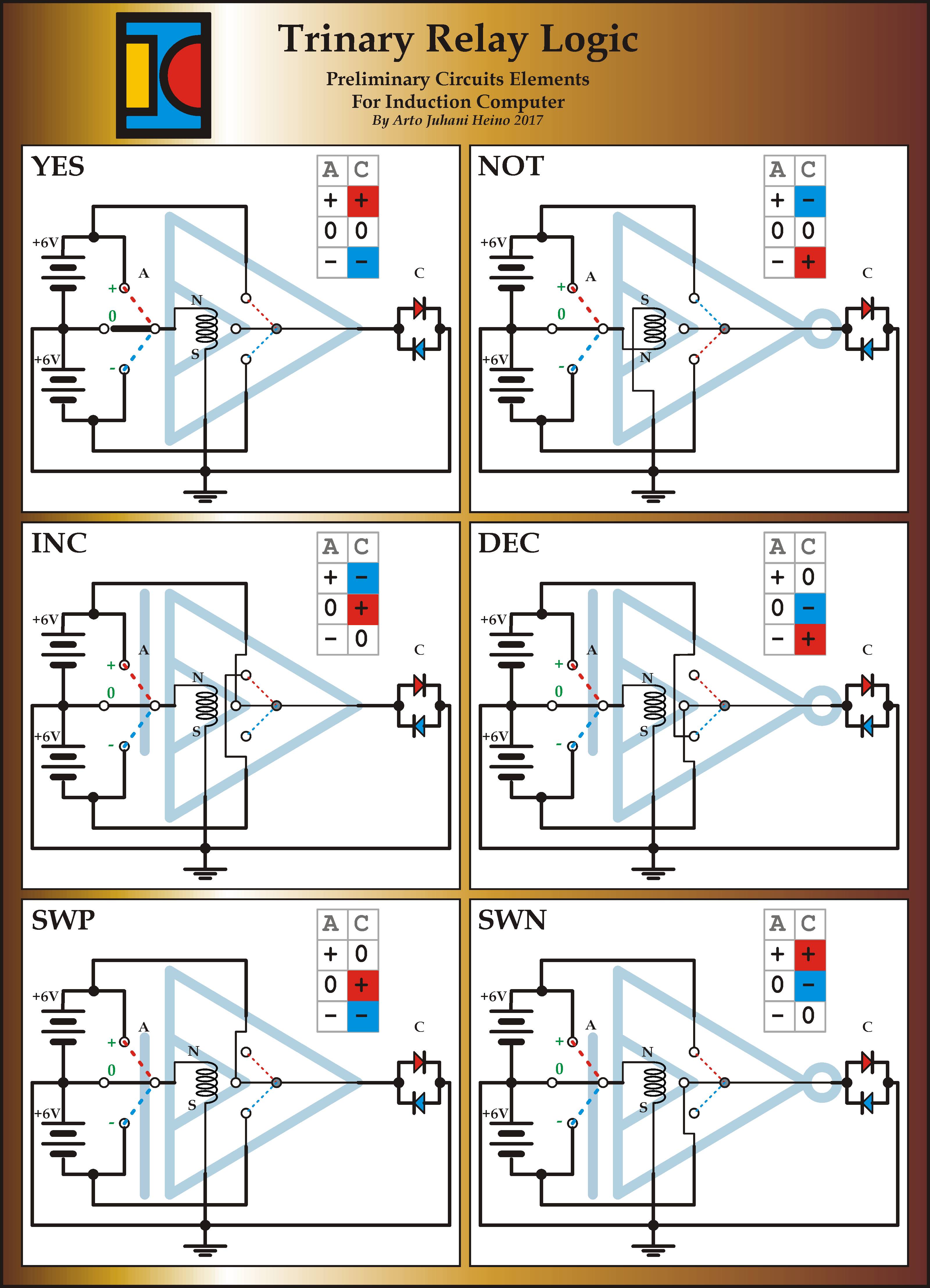
The Switch is of great importance here, the three distinct actions are of a greater Logic to apply than just on and off. The beginning of a decision tree within the three way action, yes, maybe, no. Where most will see the “0” as a null action it is a vital internal pivot to allow a current flow in be diverted for other operations, as you will see in these basic two input relay gates.

The design scheme was very involved, looking at history and to develop a version that was simple and functional, as my earlier designs show we can still lose the battery and use magnets. The next few gates tested my underlying geometry as a square 5 internal layout.

I have completed the Or, Nor, Xor and Xnor gates and the many other possible logic gates have been noted and configured for future design steps.

The ideas for using the new found parameters available haven’t been explored in the main stream forums as yet, it is not so much the answers they can provide but what are the questions we need to ask and what solutions these gates can provide, we are looking for problems that need solving, this is what will propel these ideas forward. Here is the third page of the steps to arrive at a simple Trinary system with only batteries, switches and leds.

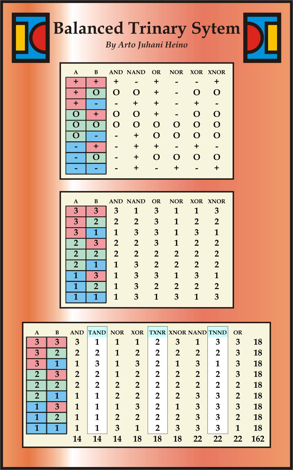
This table below shows some my more interesting breakdown of Logical Gates and new concepts of interaction with the extra three Logical operators to complete another Axiom to investigate.
(18×18)/2 = 162
162 approximates PHI
Thus in an abstracted manner, I am applying natural arithmetic, with a golden Ratio as its final Sum.
I am still working on these and will add another post soon, Regards Arto.

