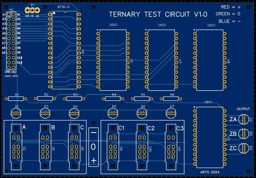
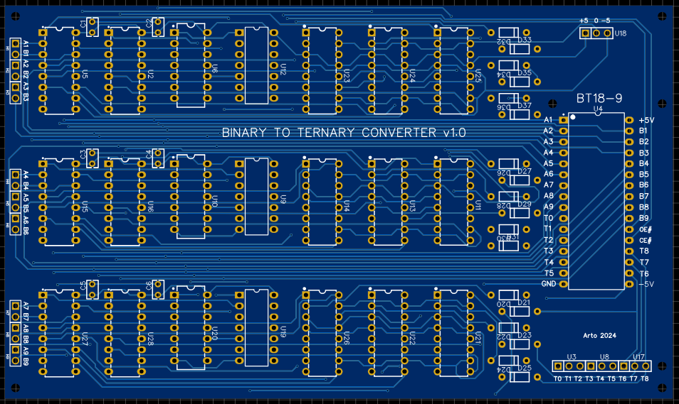
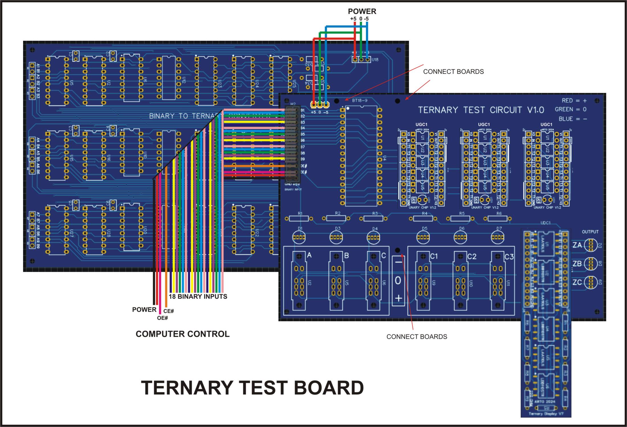
This board can accommodate 3 ternary chips the “BT18-9”, “UGC1” and “UDC1”, all of which are separate units, the BT18-9 needs either a set of ribbon cables with a socket or it can be directly connected with some HDR pins such as the connection diagram into the test board.
BT18-9
18 Binary paired Inputs (A1 B1) to (A9 B9) 9 Ternary outputs T0 to T8 OE# = output enable (you can set inputs then set to 0) CE# = chip enable (you must enable to 0 to start chip) +5V GND -5V
UGC1
1 Ternary input 1 Ternary output 1 led indictor of (-) 6 sets of programable inputs, in order
T1 T2 T3 T2 T3 T1 T3 T1 T2
T1 T3 T2 T2 T1 T3 T3 T3 T1
You can only connect 1 set at any one time, if you use a set of 3 jumper pins on all of the sets you could swap your combinations. These combinations will change your inputs into any one of six possibilities. This could also be done by using a analogue chip in a separate circuit.
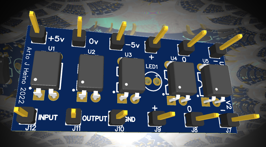
UDC1
3 Ternary inputs 3 sets of 3 colour led outputs 3 sets of 3 colour led outputs (mirror of 1st set) So you could use these as Binary output switches or sensors as required. GND V1 = +5V V2 = spare 1 (-5v)
There are 3 ternary input switches (A B C) for all three RGB outputs (ZA ZB ZC) to function, there are also 3 selectors that need to be programmed first. Two of these are programmable by a binary source, while the other is by the onboard switches (C1 C2 C3). The current footprint of the display chip is 24pin pdip, even though the board is longer. As this is still only version 7, more work to do yet and I will eventually make it fit inside the boundary similar to the UGC1 board, on version 8 or 9. I am using optical relays in this design, something that I found useful in my ternary work.
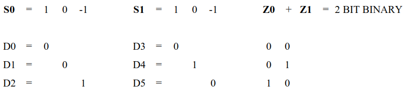
Starting from a Binary input where you have 2 bits to make a ternary trit:
00 = + 10 = 0 01 = –
The bit combination “11” is not valid and will not be used even though it is available as a binary output. The ternary converter ignores it.
Here are the 27 Unary gate combinations that are available and the binary combinations that will create them all. The UGI is the “Unary Gate Index”, numbering of all the gates in a system I have shown on my previous blogs.
Starting with the A1 and B1 as the first pair, then the A2,B2 then A3,B3, these three sets will give you a Unary set of 3 that will configure the basic Unary Chip “UGC1” to one of the 27 gates.
The second set A4,B4 + A5,B5 + A6,B6 will configure the next UGC1 gate. The third set are the switches C1,C2,C3 these will give you another UGC1 gate for you to use.
The outputs ZA,ZB,ZC correspond to the input data A,B,C, where your programmed UGC1 gate is being used to compute your result into the Z Led outputs. Where:
Red = + Green = 0 Blue = –
The input switches A,B,C,C1,C2,C3 also have RGB LEDs.
I hope this might start your interest in Ternary Logic and Computation, regards Arto.
** I have added UDC1 V8 to the Zipfile **
Ternary Test Boards PCB1D Zipfile
Al the PCB and Schematics for this project.
EasyEDA files only.
To be clear the multitude of Ternary 2 input gates is a gift to the creative mind, I have written a program that enumerates all 19683 and deemed all of them useful. An example of this is gate 2272 (TAB-index), which is “Tautology” or all “+1”, so any inputs at A and B results in +1 on the output. You might say what is the point of that? Only now it acts like a buffer or a line driver, so it serves a “function” in a ternary circuit or a re-encoder in a more complex circuit. After deciding what is needed to develop a Ternary computer, I first looked to the 27 Unary gates and the all gates that are commonly used in binary circuits, like AND, OR, NAND, NOR etc…which there are a total of 16 and which 6 are deemed the most useful.
Here is the complete set of Binary Relay Logic
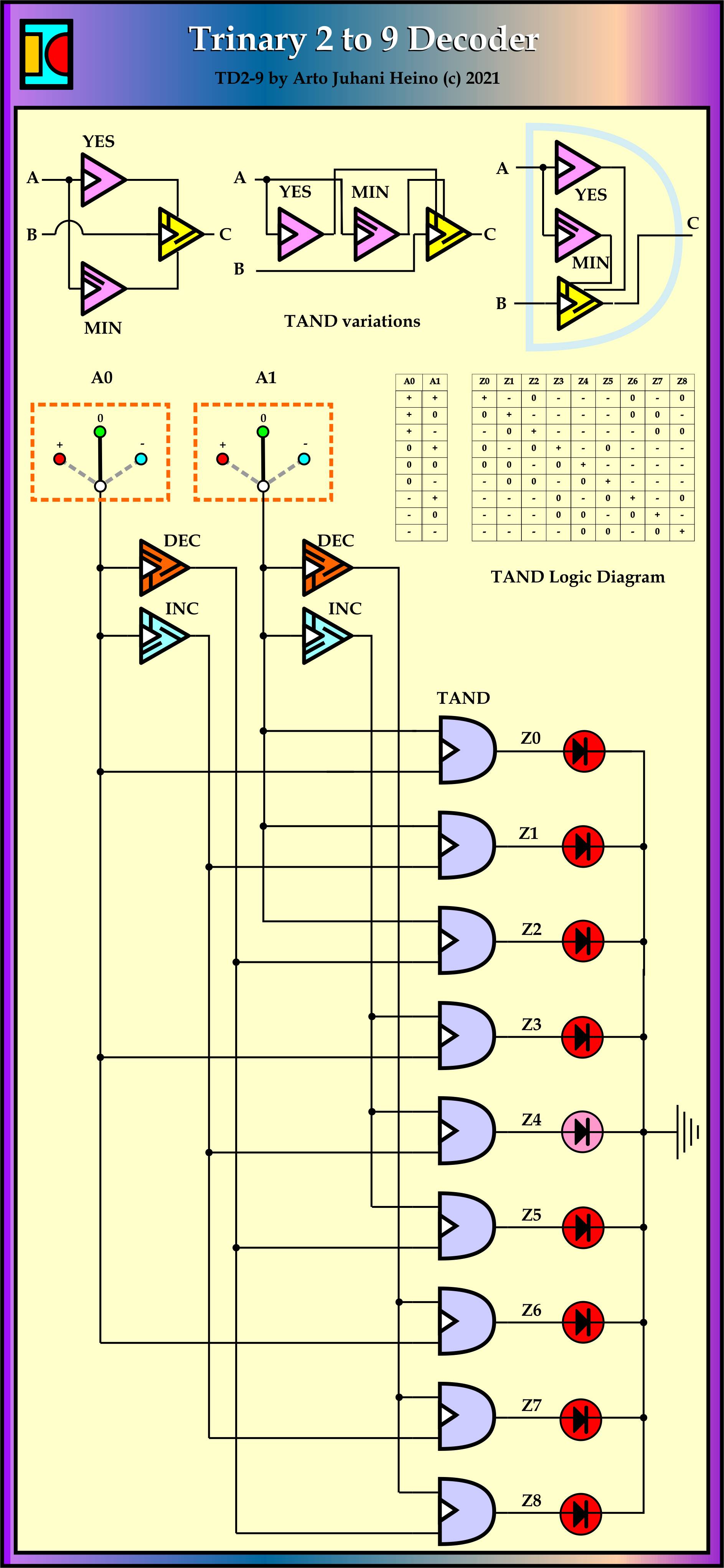
Exploring the Trinary logic opens a whole new way of seeing and thinking about computer architecture. For example a multiplexer is a most versatile device when designing circuits so I chose to explore this device to see what can be learnt from applying ternary logic to its internals. In a previous post (https://artoheino.com/2021/05/04/the-2-to-9-decoder/..) I showed my crafted and workable TD2-9 (2 input to 9 output) decoder. this will be the starting point of some new discoveries.
First lets go back to the simplest version the TD1-3 decoder:
I chose this one mainly due to the fact it can be used to decode Ternary to Binary, so one input from a Trinary based system can produce 3 signals to control a Binary based chip. So a mixture of Binary and Trinary is not difficult to attain.
Here is an example of one of my Binary to Ternary Interfaces based on a Analog Devices chip.
I have used a spread sheet to design the small Unary modules and 2 input Ternary Gate modules to develop these designs, they were based on the Ternary Relay designs I have outlined in my previous work.
The spread sheet model has helped me in developing combinatoric circuits and ensure consistent logical flow, as this is a new technological playground and has some crude pointers and intellectual fences to overcome. As the diagram of the 2 circuits show, we can decode with positive or negative numbers without the binary load that is usually a constrictive affair and become overly complex.
After much mind bending Ternary Logic visual calculations and pattern recognition, here is the First Ternary Multiplexer, TM3-1 with a future TM9-2, TM27-3 and TM81-4 as simple extensions. Where as the Binary can only achieve 2-1, 4-2, 8-3 and 16-4, so imagine how versatile these gates can be.
With this TM3-1 you could create a Ternary to binary converter, by using two of these
A Binary to Ternary converter is also possible:
They can also be usable as a 2-2 Encoder in binary:
Also by cascading the TM3-1 you can create the TM9-2.
Choice of Unary Operators
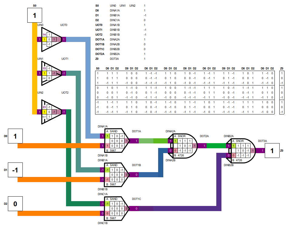
Using the binary combination of AND plus OR gates, I first applied the binary equivalents of the Ternary gates to create the Multiplexer but found the Ternary logic would not cooperate as easily as binary. This is when I realised that the ternary system would have a simpler gate choice to achieve the same result. Instead of TAND I used SAND, which has a simpler matrix, while the DNOR is similar to the TNOR gate. This gave me the start, which later I found that VAND and LAND gates also work.
Ternary 2 input Gates
Ternary Converter
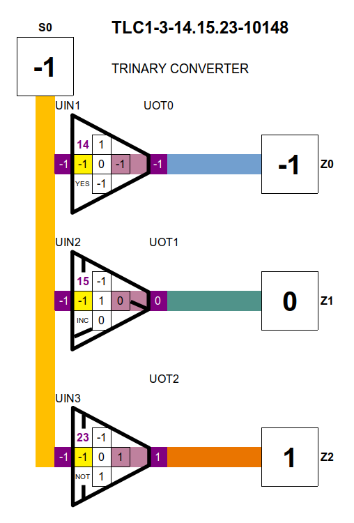
During these discoveries, I realised a ternary converter would be useful by itself. The numbering system describes the 3 gates and the 2 input equivalent.
Example:
TLC1-3-14.14.23-10148 TLC = Ternary Logic Converter 1-3 = 1 input 3 output 13.15.23 = Unary gates used 13, 15 and 23 10148 = The 2 input gate number equivalent 1 to 19686
Hardware Versions
After many attempts to make these circuits simple and easy to follow, I decided to concentrate on the relay versions but started using Photo-MOS Relays instead. This I found to be advantageous as the noise was eliminated and the current consumption decreased with the bonus of high speed. I would like to see a Photo-mos version of Programmable Logic, this would create a whole new industry, as the Photo-mos relays are already a mature technology today.
There are many manufacturers of Photo relays, lets look at the IXYS lettering, this will simplify your creative pallet. NO = Normally Open, NC = Normally Closed.
IXYS
LAA 2 in NO + NO 2 out 8 pin Dip
LBA 2 in NO + NC 2 out 8 Pin Dip
LBB 2 in NC + NC 2 out 8 Pin Dip
LCA 1 in NO 1 out 6 Pin Dip
LCB 1 in NC 1 out 6 Pin Dip
LCC 1 in NC + NO 2 out 8 Pin Dip
I opted to use the DIP 4 as well, as this would give me a more flexible layout and get different brand parts sourced and tested.
These designs cover the scope of mechanical relays, where you can configure SPST, SPDT, DTSP, DTDP different combinations, you can also have the current flow in either direction or as in neutral where there is no action to trigger the relayed combination.
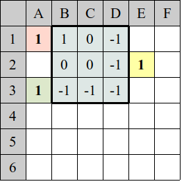
in long hand: If A1 x 10 + A3 =11 then E2 Display Value = B1
Where you would normally write
If A1 = 1 and A3 = 1 then E2 Display Value = B1 By multiplying A1 by 10 then I can add the two the values without an a “AND” logical statement while keep track if it is true or not.
Example of A3 = 1 Say if A1 = 1 then A1 x 10 + A3 = 11 A1 = 0 = 1 A1 = -1 = -9
Also if A3 = 0 Say if A1 = 1 then A1 x 10 + A3 = 10 A1 = 0 = 0 A1 = -1 = -10
And finally if A3 = -1 Say if A1 = 1 then A1 x 10 + A3 = 9 A1 = 0 = -1 A1 = -1 = -11
So you can see that the “+” in the code means “OR” , so now you have a truth table with 9 unique values. -11 -10 -9 -1 0 1 9 10 11 .The pointers are the input at A1 and A3 which define the value at E3 , altogether these are the general Logic Inputs of A B result in C.
The code for the Unary input was much simpler.
= IF(A2=1,B1) + IF(A2=0,B2) + IF(A2=-1,B3)
As you can see it is vital that your two input gates are in the correct order where as the binary version does not have that problem. Your A and B inputs and the coding of your ternary signals have a specific order which is determined by the original Truth table orientation. The convention I call “Natural” (T1) is “+ 0 -” and the Truth table is “A” rows top to bottom and “B” columns is left to right. The other options, which I have found among other ternary researchers are listed here:
By this table you can see how this effects the look of the Truth Table. So as in human relations we also have different languages in communicating, translating will not be difficult as these ideas are universal. The Non-Balanced (0 1 2) might not be as easy, as these now become arbitrary according to the designer, they might consider the “switched P” (0 + -) used as “0 1 2”, where as the “Natural” being “+ 0 -” and the equivalent would be “1 0 2”, a very confusing translation would make it difficult. This ordering is related to the voltage levels from 0 volts to 1 volt to 2 volts, this would be articulated in hardware making it incomparable with the Natural order and only interfaced through a translator. The Natural system also easily accommodates the AC wave and can be used as a clock without much difficulty.
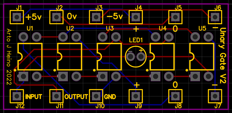
A Unary Gate Chip
The idea was to make a 12 pin bread board ready plug component that could be used to create gate combinations and test the results. Here is the UGC-V2 and a plug in header to change the Unary gate number as required. The plug-in header sits on top of the the J4 to J9 pins, it allows you to use all 27 gates. The unit is 20mm x 43mm and the plug is 20mm x 20mm.
Unary Gate Chip
I hope this spurs some interesting Ternary work and we might see a bright future in using “LIGHT” as the interface between the old Binary Paradigm to the new Trinary way of doing things. Regards Arto.
The completion of the trinary understanding in relays has been very rewarding, this is my first attempt at a trinary decoder chip version of the 3-8 decider 74138, where a 2-9 decoder TD2-9 is a trinary designed device that would also do the job. It could be fabricated with FETs and miniaturised so it fits onto existing chip boards.
As I see this as my first step into making useful and efficient circuitry based on trinary inputs and easily adapted to the standards in current use. I see great promise in adapting trinary systems to current binary as a step into integration. These ideas are adaptable and flexible to be used in some AI systems. even now.
The long dreamed idea of a trinary system was to advance understanding of natures logic and repair the mistakes made in the service of short gain which is full of hubris and greed. Current digital systems can be 256 wide, but not in most cases they run 64bit and 32bit subsystems even some 16 and 8 bit are in the mix, is all due to the through put required by graphic chips to reduce time lags and memory bottle necks with all that constraint issues.
These behemoth super computer systems are complex to design and control. let us look some maths.
Binary Trinary
0………+ 0 – 2 bit…….3 trit 4 bit…….9 trit 8 bit…….27 trit 16 bit…..81 trit 32 bit…..243 trit at this point we have reached beyond our current systems 64 bit…..729 trit 128 bit…2187 trit 256 bit…6561 trit 512 bit…19683 trit As you can see that 64bit computing is the norm at present and moving into 128bit at lighting pace. Where we could have reached 729 trit in the same time frame. imagine the 64bit super cellphone you hold in your hand would have been the norm in 1980’s. This is the amount of development retardation we were forced to endure due to short sightedness and unripe understanding of all the future issues at hand. This simple list shows one aspect, here the binary decoder version
So a 3 to 8 decoder has the trinary equivent of the 2 to 9 decoder, if we ueed 3 inputs we would arrive at 27 outputs, the advantages are simple.
Trinary Inputs and Trinary outputs Trinary Inputs and Binary outputs Binary Inputs and Binary outputs Binary Inputs and Trinary outputs 1___3……..TD1-3 2___9……..TD2-9 can also act like two of 4 bit dual level logic (2 Only gates make a Sure gate) 3___27……TD3-27 4___81……TD4-81 5___243….TD5-243 6___729….TD6-729
There are no off the shelf trinary chips to build useful devices from these decoders as yet.At this present form(very large relays) you could apply these trinary systems to AI of the grid system, where self regulation with the enviroment is required and not optional. As you are dealing with an Earth that has all three parts of the trinary logic, the Sky, the surface and Inner Earth, as ” + 0 – “. I have extended the understanding here to illustrate our well of energy we walk upon.
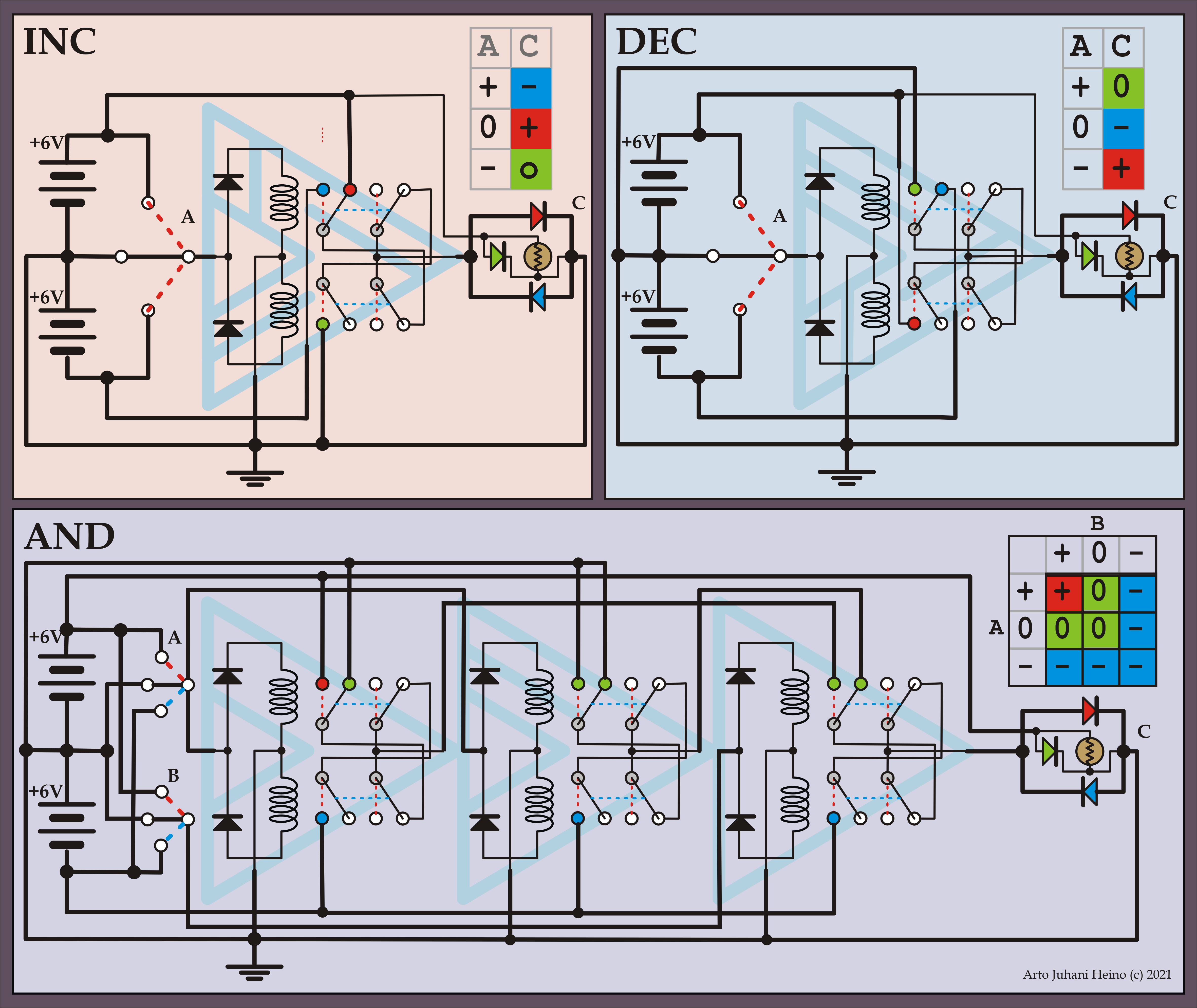
This diagram illustrates the relay design of the three different trinary gates you need here. You can make the relays a small or big as you need . Everything here is simple and easily built on you electronic bench, please feel free to use these gates in a project.
INC and DEC gates and a TAND gate
As now I have decided upon my choice of trinary AND gates, which there are a few, the TAND gates now lives amongst my circuit ideas. More decoders and encoder to be illustrated very soon.
TD2-9 Trinary Decoder
Here is the place this circuit will live, 2 of these to drive the 16 pin 8 x 8 led matrix (ADM-388C0). How simple is that, 4 trinary trits control 81 LED locations, 64 for the Matrix and 17 for other things.Regards Arto.
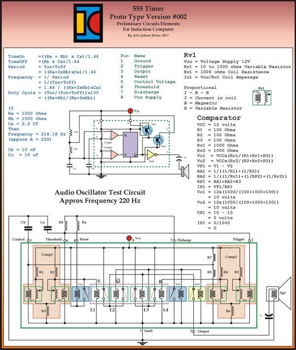
I am back from the wilderness, the experiences of Spring has overwhelmed my Audio and Visual organs, natures beauty is beyond any simple description. The last post I never mentioned the Trinary system that took my designs closer to a complete new type of thinking to develop a Trinary ALU, much more interesting than the Binary approach. Here is the 555 timer I promised from the last post, it is closer to a build-able relay design than my first prototype.
I didn’t show any parameters for the Basic Logic Cell. Here is my sizes and reasoning:
The Basic Logic Cell – Logical Unit
Working from the true measure the Royal Cubit approx 523.24mm, rounding to 525mm. The Palm is four fingers and seven palms make the Royal Cubit.
75mm x 75mm Sqr (aprox 3″ x 3 “)= 1 square Palm.
18.75mm Thick(rounding to 19mm, aprox 3/4” ) = 1 finger thick.
This was why I chose the Ancient Royal Cubit, when you measure the longitudinal velocity of light in royal cubits equals exactly 900000000. Thus it is the exact measure of the Royal Cubit.
Velocity of Light = C
= 299792458 mtrs sec
Longitudinal Velocity of Light = Pi/2 x C
= 1.5708 x 299792458
= 470912891.8272 = CL
Therefore
= CL/900000000
=470912891.8272/900000000
= 0.5232365 Mtrs
= 1 Royal Cubit
This means all your measures you use on materials is concordant to a universal standard, so by coordinating Electrical, Sonic and Hydraulic wave forms in your Logical Unit, all the impedance issues would be known, thus engineer-able.
The Universal Binary Engine
To complete my journey back to relays here is one draft of the Universal Binary Engine, it was designed to be used with a rotary commutator in mind, I was considering the technology of 1900 and the implementation of the Tesla tower as a the hub of computing the Longitudinal Ground Wave communication traffic he would have had to encounter if his tower was finished. Here are my preliminary data covering the commutator and/or relay computer. I have dubbed it “The Universal Binary Engine“, it has motoring logic built in, so a rotating system is viable, a whole new way of conveying intelligence through simple matrix connections with commutators , setting up codes for binary transmission in as many bits as needed. This would be similar to the type of computer switching system Tesla could have worked out during his Wardenclyff period, to direct the control of a complex communication system, with subscribers numbering into the hundreds of millions, not bad for pre-transistor or valve era. Each bit would be just another commutator in rows of switching array commutators, this way you can accommodate large address locations on the globe using a whole wave node number(Earth circumference wave number derived from the frequency of operation) and the directions NSEW as your location matrix. I have a vision in my mind regarding the operational frequencies and mechanical rotating frequencies to make such a system operate as a World Wireless System (NOT Radio), here is a draft PDF of one of my ideas. Here. As this was about laying the most simplest wiring and layout, where you could his own switching systems as per Patent 685953, as illustrated in my Volume I, page 343. I always draft my original designs by free hand sketches and hand written work books, while I am design the Trinary version as well this way, I only draw my work on computer long after I have cleared up any mistakes, either physically tested or carefully worked out on spread sheets.
Trinary
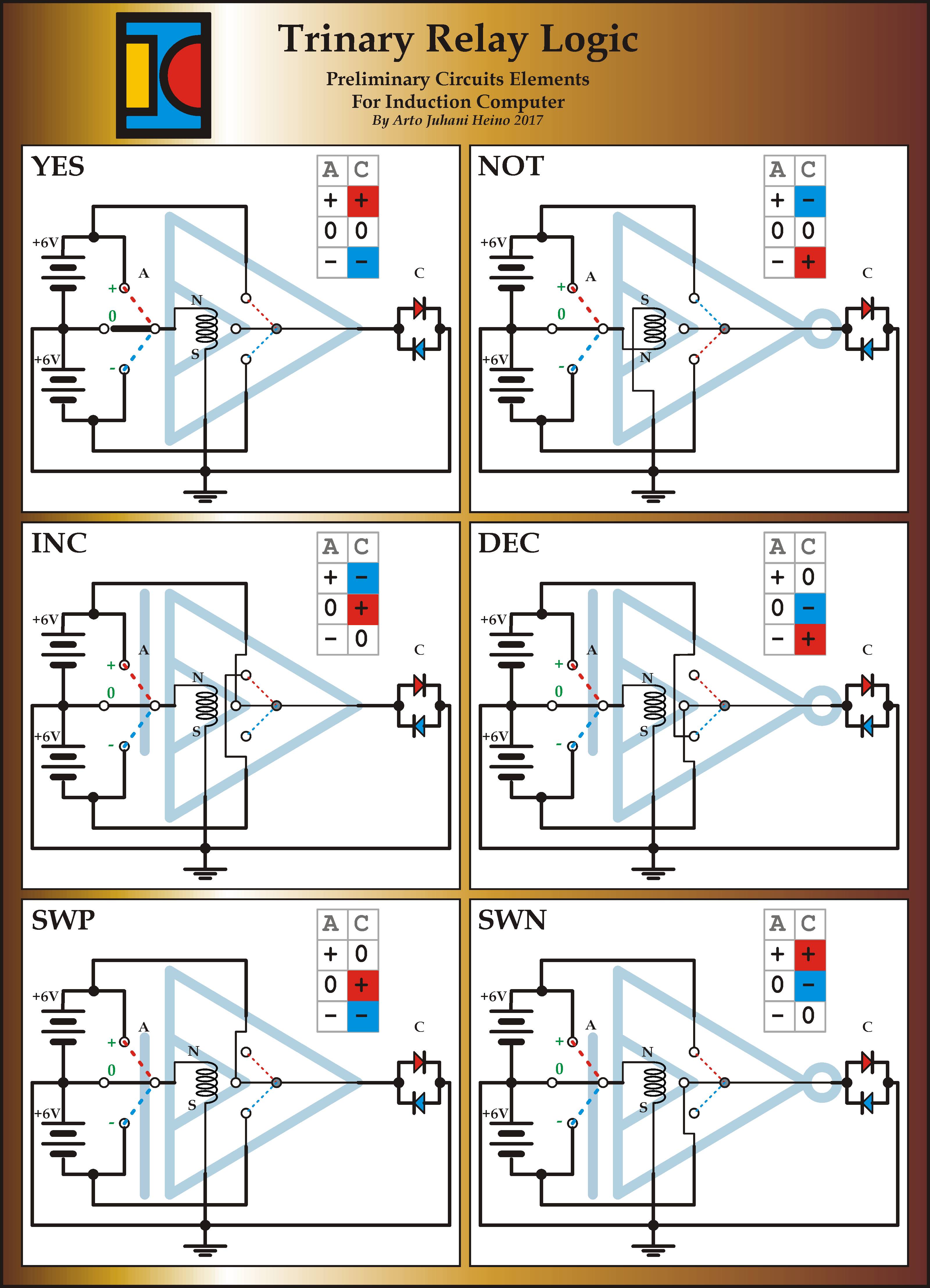
Here is list of the first 6 Trinary single input logic gate operations, there are more that I will list shortly.
The Switch is of great importance here, the three distinct actions are of a greater Logic to apply than just on and off. The beginning of a decision tree within the three way action, yes, maybe, no. Where most will see the “0” as a null action it is a vital internal pivot to allow a current flow in be diverted for other operations, as you will see in these basic two input relay gates.
The design scheme was very involved, looking at history and to develop a version that was simple and functional, as my earlier designs show we can still lose the battery and use magnets. The next few gates tested my underlying geometry as a square 5 internal layout.
I have completed the Or, Nor, Xor and Xnor gates and the many other possible logic gates have been noted and configured for future design steps.
The ideas for using the new found parameters available haven’t been explored in the main stream forums as yet, it is not so much the answers they can provide but what are the questions we need to ask and what solutions these gates can provide, we are looking for problems that need solving, this is what will propel these ideas forward. Here is the third page of the steps to arrive at a simple Trinary system with only batteries, switches and leds.
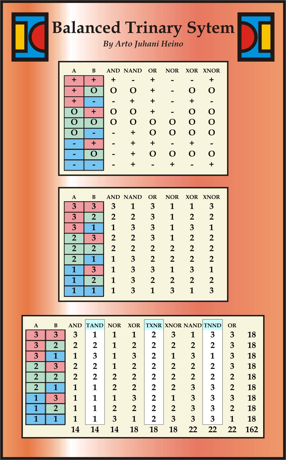
This table below shows some my more interesting breakdown of Logical Gates and new concepts of interaction with the extra three Logical operators to complete another Axiom to investigate.
(18×18)/2 = 162
162 approximates PHI
Thus in an abstracted manner, I am applying natural arithmetic, with a golden Ratio as its final Sum.
I am still working on these and will add another post soon, Regards Arto.
Talking to the Birds
Book Available NOW
At Amazon
At Createspace
https://www.createspace.com/4513692
______________________
Cartoons
http://www.scribd.com/doc/106684504/Scraps-Sketches-and-Satire
_______________________
Magic Square
http://www.scribd.com/doc/33050524/The-Magic-Square-of-Three-Crystal


