To be clear the multitude of Ternary 2 input gates is a gift to the creative mind, I have written a program that enumerates all 19683 and deemed all of them useful. An example of this is gate 2272 (TAB-index), which is “Tautology” or all “+1”, so any inputs at A and B results in +1 on the output. You might say what is the point of that? Only now it acts like a buffer or a line driver, so it serves a “function” in a ternary circuit or a re-encoder in a more complex circuit. After deciding what is needed to develop a Ternary computer, I first looked to the 27 Unary gates and the all gates that are commonly used in binary circuits, like AND, OR, NAND, NOR etc…which there are a total of 16 and which 6 are deemed the most useful.
Here is the complete set of Binary Relay Logic

Exploring the Trinary logic opens a whole new way of seeing and thinking about computer architecture. For example a multiplexer is a most versatile device when designing circuits so I chose to explore this device to see what can be learnt from applying ternary logic to its internals. In a previous post (https://artoheino.com/2021/05/04/the-2-to-9-decoder/..) I showed my crafted and workable TD2-9 (2 input to 9 output) decoder. this will be the starting point of some new discoveries.
First lets go back to the simplest version the TD1-3 decoder:

I chose this one mainly due to the fact it can be used to decode Ternary to Binary, so one input from a Trinary based system can produce 3 signals to control a Binary based chip. So a mixture of Binary and Trinary is not difficult to attain.
Here is an example of one of my Binary to Ternary Interfaces based on a Analog Devices chip.

I have used a spread sheet to design the small Unary modules and 2 input Ternary Gate modules to develop these designs, they were based on the Ternary Relay designs I have outlined in my previous work.
The spread sheet model has helped me in developing combinatoric circuits and ensure consistent logical flow, as this is a new technological playground and has some crude pointers and intellectual fences to overcome. As the diagram of the 2 circuits show, we can decode with positive or negative numbers without the binary load that is usually a constrictive affair and become overly complex.
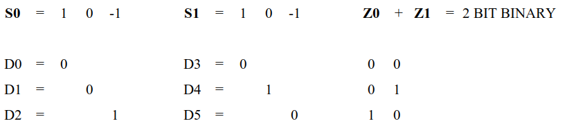
After much mind bending Ternary Logic visual calculations and pattern recognition, here is the First Ternary Multiplexer, TM3-1 with a future TM9-2, TM27-3 and TM81-4 as simple extensions. Where as the Binary can only achieve 2-1, 4-2, 8-3 and 16-4, so imagine how versatile these gates can be.
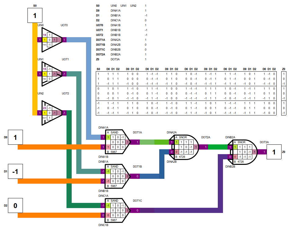
With this TM3-1 you could create a Ternary to binary converter, by using two of these
A Binary to Ternary converter is also possible:

They can also be usable as a 2-2 Encoder in binary:

Also by cascading the TM3-1 you can create the TM9-2.
Choice of Unary Operators
Using the binary combination of AND plus OR gates, I first applied the binary equivalents of the Ternary gates to create the Multiplexer but found the Ternary logic would not cooperate as easily as binary. This is when I realised that the ternary system would have a simpler gate choice to achieve the same result. Instead of TAND I used SAND, which has a simpler matrix, while the DNOR is similar to the TNOR gate. This gave me the start, which later I found that VAND and LAND gates also work.

Ternary Converter
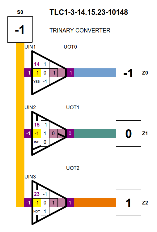
During these discoveries, I realised a ternary converter would be useful by itself. The numbering system describes the 3 gates and the 2 input equivalent.
Example:
TLC1-3-14.14.23-10148
TLC = Ternary Logic Converter
1-3 = 1 input 3 output
13.15.23 = Unary gates used 13, 15 and 23
10148 = The 2 input gate number equivalent 1 to 19686
Hardware Versions
After many attempts to make these circuits simple and easy to follow, I decided to concentrate on the relay versions but started using Photo-MOS Relays instead. This I found to be advantageous as the noise was eliminated and the current consumption decreased with the bonus of high speed. I would like to see a Photo-mos version of Programmable Logic, this would create a whole new industry, as the Photo-mos relays are already a mature technology today.
There are many manufacturers of Photo relays, lets look at the IXYS lettering, this will simplify your creative pallet. NO = Normally Open, NC = Normally Closed.
IXYS
LAA 2 in NO + NO 2 out 8 pin Dip
LBA 2 in NO + NC 2 out 8 Pin Dip
LBB 2 in NC + NC 2 out 8 Pin Dip
LCA 1 in NO 1 out 6 Pin Dip
LCB 1 in NC 1 out 6 Pin Dip
LCC 1 in NC + NO 2 out 8 Pin Dip
I opted to use the DIP 4 as well, as this would give me a more flexible layout and get different brand parts sourced and tested.
These designs cover the scope of mechanical relays, where you can configure SPST, SPDT, DTSP, DTDP different combinations, you can also have the current flow in either direction or as in neutral where there is no action to trigger the relayed combination.
The Spreadsheet Logic Code
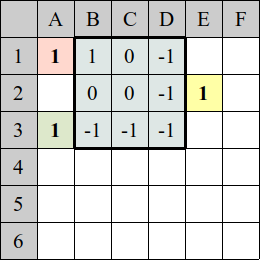
This code is Located at E2
=IF(A1*10+A3=11,B1) + IF(A1*10+A3=10,C1) + IF(A1*10+A3=9,D1) +IF(A1*10+A3=1,B1) + IF(A1*10+A3=0,C1) + IF(A1*10+A3=-1,D1) + IF(A1*10+A3=-9,B1) + IF(A1*10+A3=-10,C1)+ IF(A1*10+A3=-11,D1)
Lets break this down:
The first part of the code
If(A1*10+A3=11,B1)
in long hand:
If A1 x 10 + A3 =11 then E2 Display Value = B1
Where you would normally write
If A1 = 1 and A3 = 1 then E2 Display Value = B1
By multiplying A1 by 10 then I can add the two the values without an a “AND” logical statement while keep track if it is true or not.
Example of A3 = 1
Say if A1 = 1 then A1 x 10 + A3 = 11
A1 = 0 = 1
A1 = -1 = -9
Also if A3 = 0
Say if A1 = 1 then A1 x 10 + A3 = 10
A1 = 0 = 0
A1 = -1 = -10
And finally if A3 = -1
Say if A1 = 1 then A1 x 10 + A3 = 9
A1 = 0 = -1
A1 = -1 = -11
So you can see that the “+” in the code means “OR” , so now you have a truth table with 9 unique values. -11 -10 -9 -1 0 1 9 10 11 .The pointers are the input at A1 and A3 which define the value at E3 , altogether these are the general Logic Inputs of A B result in C.
The code for the Unary input was much simpler.

= IF(A2=1,B1) + IF(A2=0,B2) + IF(A2=-1,B3)
As you can see it is vital that your two input gates are in the correct order where as the binary version does not have that problem. Your A and B inputs and the coding of your ternary signals have a specific order which is determined by the original Truth table orientation. The convention I call “Natural” (T1) is “+ 0 -” and the Truth table is “A” rows top to bottom and “B” columns is left to right. The other options, which I have found among other ternary researchers are listed here:

By this table you can see how this effects the look of the Truth Table. So as in human relations we also have different languages in communicating, translating will not be difficult as these ideas are universal. The Non-Balanced (0 1 2) might not be as easy, as these now become arbitrary according to the designer, they might consider the “switched P” (0 + -) used as “0 1 2”, where as the “Natural” being “+ 0 -” and the equivalent would be “1 0 2”, a very confusing translation would make it difficult. This ordering is related to the voltage levels from 0 volts to 1 volt to 2 volts, this would be articulated in hardware making it incomparable with the Natural order and only interfaced through a translator. The Natural system also easily accommodates the AC wave and can be used as a clock without much difficulty.
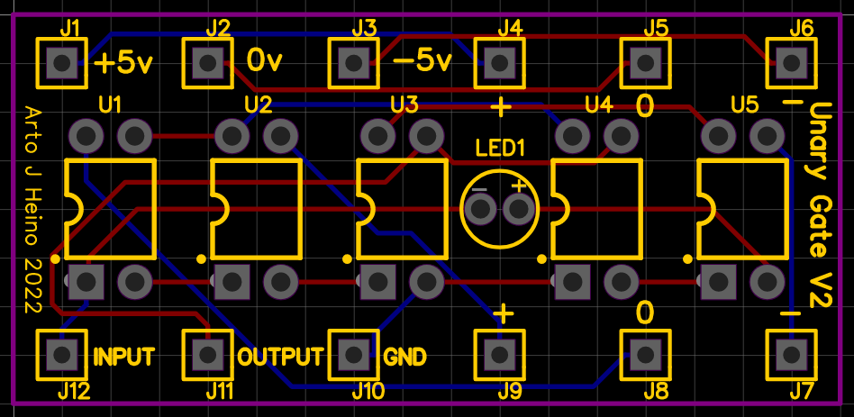
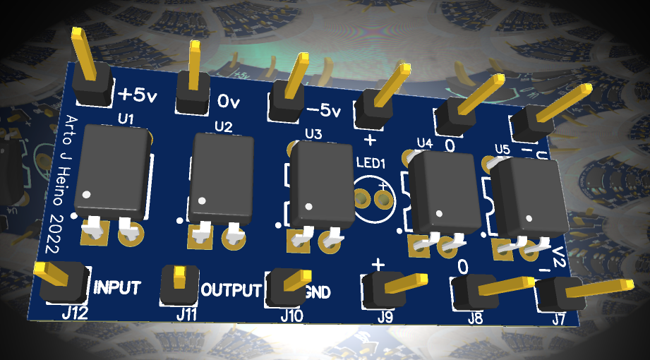
A Unary Gate Chip
The idea was to make a 12 pin bread board ready plug component that could be used to create gate combinations and test the results. Here is the UGC-V2 and a plug in header to change the Unary gate number as required. The plug-in header sits on top of the the J4 to J9 pins, it allows you to use all 27 gates. The unit is 20mm x 43mm and the plug is 20mm x 20mm.
I hope this spurs some interesting Ternary work and we might see a bright future in using “LIGHT” as the interface between the old Binary Paradigm to the new Trinary way of doing things. Regards Arto.
Tags: 19683, binary, decoder, multiplexer, photo-mos, relay, ternary, trinary

Leave a comment