Hi to all my readers,
As of the year 2021 , we are all a witness to the living totalitarian nightmare, one that had haunted my dreams and visions since the early 70’s, most of my friends thought, that much of what I have said back then, to be conspiratorial and fanciful, I assured them, that history has been rewritten, to what end I didn’t know, I suspected it was nefarious, possibly to create a War that would destroy countless millions of lives. I was the outlier who read a lot of books mainly very old books in the library after school and what I didn’t read I borrowed and read over the next few nights, I did wonder why the encyclopedias were up dated every 10 years or so, as the information was the same, so I assumed it was the new data they added, only to find out they deleted and reedited many events and solid data, to be rewritten to imply a different narrative and point of view, a slow brainwashing. TV was not a good source of real information either, it never seem to align with history as was written, it always had twists and turns that never occurred, they called it artistic licence, later without edits to be taken as fact, especially surrounding WWII, the 1918 Spanish Flu and anything about the forming of the United Nation and the US Federal Reserve. In a summary of this type of editing, the Cultural Marxists in bureaucracy edited to their hearts content, filling nuances with political double speak and removing figures and deeds that goes against the main Marxist narrative. For an example, Merriam Webster online dictionary edits the meaning of words regularly, they changed the meaning of Vaccine recently, we know it’s the Cabal who wants to own the words, so who owns the dictionary. (OWN = NWO, mirror word)
I wrote a poem in High School (1969), “A War That Should Never Be”, it was a prophetic vision of things I glimpsed at in a dark future, not something I wished and hoped we would ever go to, especially after reading Brave New World, 1984 and other Science Fiction stories. After leaving school I worked in News Ltd as a copy-boy, I was curious how the News cycle was implemented and wanted to learn more, mainly after reading a lot about the history of the publishing industry, especially its machinery, inventors and such. The political alignment of the News Corporations was not in my sights or my concern, as a young Artist it did not matter, people were people, at the time I did’t realise the collapse of the Arts occurred a long time ago.
After working there, I became equated with Paul Rigby and Bruce Petty, the two Artist that drew the page three cartoons, much was newly understood and as a young mind I vacuumed every tid-bit. I did learn one thing that changed my ideas about the world, the top down approach was in full swing in the early 70’s much like it has been in the last 100 years, Reuters was owned by the Rothschild’s at the time and this I gathered was why the news I read from copy became propaganda with a object to either ridicule the subject or twist the narrative to conform to a hidden script, being too young to understand what I was looking at, I decided that this industry was not my cup of tea, Fake News was a well oiled machine and I didn’t want to be part of it, the discovery of facts and truth was far removed from the modern journalists vocation, it only lived in my own version of an ethical and unsullied journalists philosophy. Meeting Rupert Murdoch was possibly a notable event for a 16 year old, it impressed upon me the power one man could yield if they control the flow of information, he encouraged my pursuits in the art department and wished me success, this seems like the devil was giving me encouragement.

I watched the Vietnam War in the 60’s, with it ending there was a mass dispersal of Vietnamese refugees world wide, it did not make sense, why would you send people out of the country when you needed them to rebuild it? I guessed that the UN had some sort of agenda. After much thought and clear facts of history that it was clear that mass migration was one of the tools to destroy Nations, for both host and donor nations. My family migrated from Finland in 1959, I was aware of the whole problem, as a child I asked my dad, “why did we come here (Australia), this is not as nice as home?”, my dads reply was straight forward and without candy, “After the war, we had to pay half our salary as reparations for losing the war against USSR, this means working 16 hour days, Australia offered a nice immigration plan so we can start again.”. I discovered later that my dad was right, the average Finnish man died in his 50’s due to this massive burden, sadly my father died at 55 here in Australia from much of what happened in the war, it was a pity that we never returned to Finland even though the debt was paid, but the people never completely recovered from the burden of sustained excess work load.
Here is a list of manufactures items, that should give you an idea how much the Finnish men had to toil after the war in which they suffered to support, feed a family and work ridiculous hours to comply with the USSR demands. Remember this was a country of only 4 million people. Here are some of the deliveries made:
52,500 electric engines
1,140 transformational stations
30 mills with power stations
525 narrow gauge locomotives
76 units of modified Railway engines to 750mm gauge
619 vessels
7 ice breakers
91 of 300 tonne schooners
37208 railway wagons of wooden house materials
520 complete wooden houses
So many years have passed since my youth and many struggles to understand our world lay before me, never knowing why the goal posts of a great and enlightened society kept moving further away. I was born with gifts that obliged me to pursue my artistic goals, singing, drawing, painting and poetry were activities that I was exemplary in, so this was the direction I focused upon. Science, Mathematics, Geology, Astronomy and Engineering was essential to my understanding of the world and the artistic goals that was driven by my psych, where all the great Artists from history of mankind was my measure. At this point I realised that parts of the Sciences was being misdirected by a cabal of dis-informants bent on destroying our civilisation. As I later discovered it has already been partially destroyed by the Universities and Colleges a long time ago, there was only outliers who knew the full truth, this revelation was not known by me until I was in Art school and met the Marxist indoctrinators in person and how they operated, still in hindsight, it seemed America had many who knew the hidden agenda, as I had been an avid reader of the underground fanzines and rare tabloids.
This was a defining period where my suspicions were being confirmed as to the motives of a hidden cabal that I knew very little of. I chose not to enter the system of lies and misinformation, as my instincts told me it was a poison that I could not recover from, Art was not meant to perpetuate lies and incorporate a destructive ideology that would surely destroy many lives and the true history. Art has always been historically a vocation to reveal the truth and the show the understanding of the universe. This impasse was to make me rediscover the past and try to rebuild an ancient knowledge long forgotten that had sustained many civilisations for millennia, a world of new discovery lay before me, I only needed to redefine a mental filter that would allow me to see past all the deceptions the cabal had built into the multiple “systems” and bureaucratic layers of our society. I now walked in a mine field, full of distractions, detractors, indoctrinators and the disbelievers of the hidden agenda that was trying to destroy a dream of a common sense, healthy and fulfilling way of life. Pointing out the totalitarian defects of the UN world system of governance to others, was met with me being labelled as a “conspiracy theorist” or I was “out there”, so I held that as a badge of honour, as they could see nothing and they never questioned anything, how the tide has turned, all those detractors are living in a Fear induced psychosis.
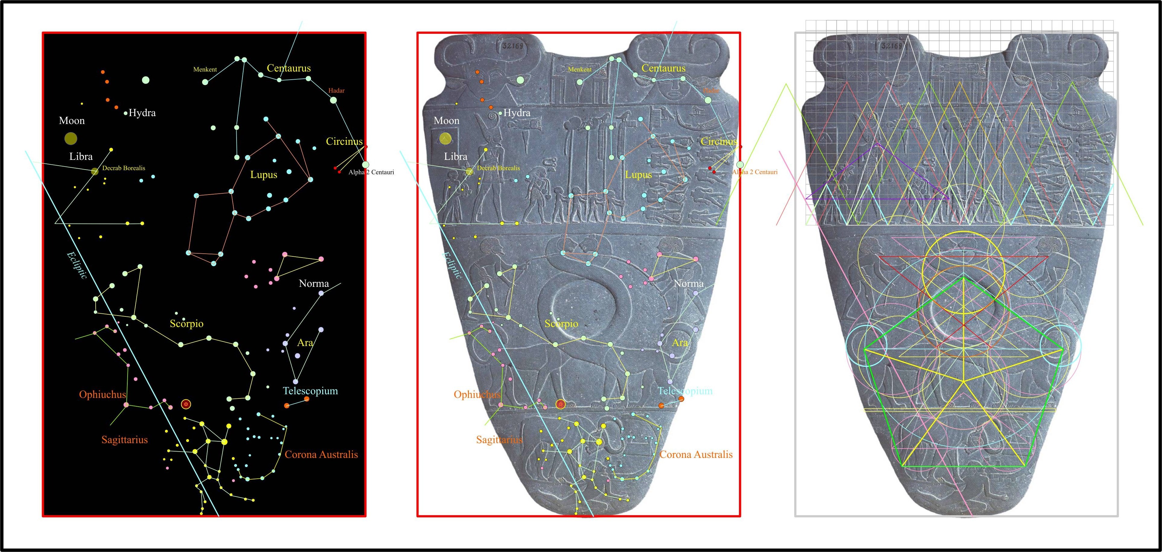
First I had to rediscover my own time line, where I stood in the moulding of culture that had been taking place in my lifetime and in my generation. I thank my primary school teacher for encouraging me to express much of my innate artistic nature, this is where I rediscovered the Art and Architecture of Gothic and the Renaissance, which owes its heritage to ancient Greece and Rome, which intern owes it to the remnants of Ancient Egyptians and the Temples and Vedics of India, while the ancient Europeans seemed to have been lost somewhere in a deluge. The timelines of history did not give a clear path of our past, it seemed the older the Civilisation, the greater the accomplishments. I was at this juncture that I realised we had spiritually, mentally and intellectually fallen somewhere in the past (500AD) to very low barbaric times we call the “Dark Ages”, while subject to a form of global amnesia and was slowly regaining many technologies to create a more functional society over the centuries.
At this point I could see the cyclic nature of Civilisations, not as the history books codify as a slow progress from the caveman to agriculture then villages then nations or the three stages of civilisation before its downfall, as in the written version of the fall of the Roman Empire and others. The complete cycle was a long 25000 years and simply followed the Zodiac in its ages and character of their times, research the “Yuga Cycle” to clarify what I am indicating. The Egyptian history itself defied many typical historic narratives, showing clearly that the older the artefacts and buildings the greater the precision and technology, something did not fit. The multitude of Ancient Indian Temples, Meso-American buildings also show this same pattern, this was to finally make all the history books become so much wasted paper, full of assumptions, lies and founded in a poorly scripted narrative. Much fantasy that appealed to many doubters, such as Aliens, time portals and many other stories would be exploited by Hollywood, Comics and tabloids, again to keep the truth seekers from uncovering how our society has been misdirected to push us into the occult New World Order, now openly admitted in public discourse, as it is no longer a “Conspiracy Theory”, it is an open conspiracy and we all know the facts, less is hidden every year.
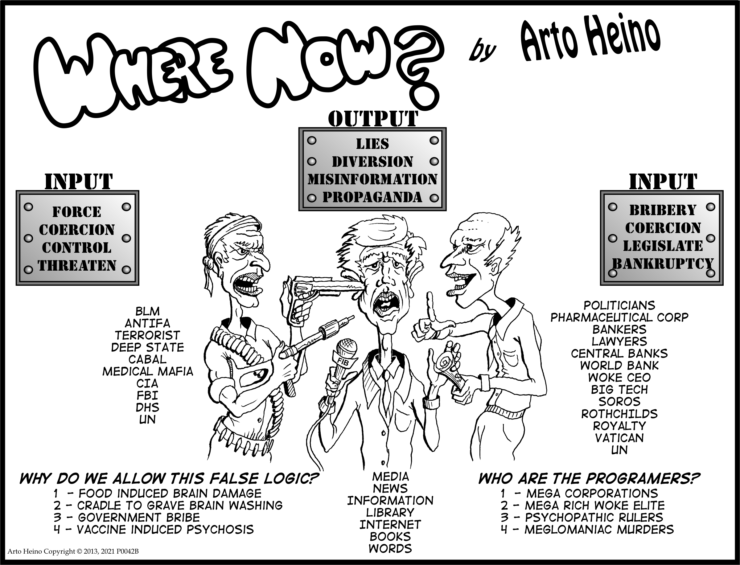
So what does one say to his friends and family about the world you have discovered many years ago that they are not aware of, “not much”, as I found out by trying to explain to others the complex web of lies that are wound on almost every historic, scientific and cultural event. So I decided to create Memes and Cartoons that expressed much of what I know in a simplified way. The role of the classical Artist would be to create large artworks with historical figures, showing symbolic gestures, symbolism, dramatic poses and scenery that show a complex orchestration of thematic material and show the state of the world and it conflicts, This genre is still open to me and I will proceed with such a work in the future when my living conditions are right, at present the battle is still in progress and the demarcations lines of dramatic revelations have not been drawn as yet. This is called the “Historic” genre and is much more complex now than anytime in recent history.
The cartoon series I started called “Where Now?” was a small attempt to recover what page three Artists did for the last 100 years, excluding the last 20 years were it has been scrubbed, due to its revealing nature, creating a problem for the New World Order dictated press. I then drew, usually in one sitting and generally without any sketches and directly with ink. So I continued with it adding a few of my artistic ideas, like “Mic Oligar”, “Random Choices”, “Statistical Reality”, “Counter Actions”, “Apathy”, “The Scammer”, “The Odd Ball Inventor”, “Synthonyms”, also creating “Memes” and rebuilding comic, newspaper and magazine covers with new insightful messages. So much fruitful resources I could gather from the bread crumbs of the Psychopaths that were trying to reshape the world. I stopped my cartooning in 2017 as I realised that the Big Tech platforms and the Deep State were trying to destroy many voices that were waking up the public to the many lies, imminent dangers and false narratives in our society.
They have declared War on the public mind by criminal lies printed as truth in the main stream media, I was not going to be silenced because I was prodding the NWO Hydra, so I took another path, much more suited to my talents, to unwrap the history and technology of the Ancient past. Speculation on the past was not so offensive to those who already have dismissed you as a outsider. My contributions to the counter narrative has been to clarify some solutions and open a door to creative expression, by adding a few vernaculars to the mix such as “Demonrat”, “Conspiracy No More” , “Illusion of Democracy”, “6uild 6ack 6etter”, and many more, now used to describe complex memetic ideas. This unravelling of the ancient past was to establish a direction we could reformulate to build a system that could not be corrupted by psychopaths or those with dark and unsavoury influence that corrupt society, like Soros.
If you want a Tshirt from Red Bubble that show you the three state NWO hazard proof click here.
https://www.redbubble.com/i/t-shirt/NWO-Hazard-by-ArtoJ/8093502.UIV3X
I would rather paint, draw and sculpt than engage in Memes, Satire and critiques of modern society, it is just they have left me no choice, the Cabals outreach had destroyed our Art institutions and replaced them with degenerate Marxist trash. It sure sounds harsh, but it is the softly softly approach that causes the most damage to the minds of the youth, by filling them with unrealistic promises that only lead to self destruction. Giving them praise in matters when they have truly failed, encouraging training and rote learning over understanding and no self criticism or reflections on any mistakes, these are recipes for a society of ineptitude and weak moral fibre. We are not perfect, this is a truism, regardless we still should strive for proficiency, mental finesse and holistic understanding of our chosen vocation. Four years of Medical School might make you a Doctor in Certification but does it render your heart and soul to a Qualification that only the spirit of honesty and true empathy can tender. A Technician in not an Engineer, the Technician applies rule based algorithms while the Engineer applies deep understood principals of Science, Technology and life experience. Does this also apply to Politicians? What qualifies a Politician to be able to apply policies that the majority of people demand? Is it his ability to use words and organise the resources for the benefit of the people, yes, this is their imperative but is it what they all actually do in real life? How can a politician become very wealthy if they are on a government salary, they cannot use their influence to dabble in stocks or property to benefit their financial position, this is immoral behaviour and is surely illegal but that is what they do, in cloak of darkness and by proxy.
The term “Red Pill” as a wake up call for conscious return to reality was taken from the movie “The Matrix”, the title was a synonym for the Cabal or the Deep State. The “Blue Pill” was “woke” version of reality, a zone of phantom racism, rampant misogyny, open borders, gender fluidity, no police, free everything and nobody has to work, as this is the weak low expectation philosophical fantasy world they are told exists if we choose it, first get the jab. As history will show the first openly subversive organisation to pose as a surrogate of the Cabal was “The League of Nations” back in 1920. The LON had a charter and demanded a solidarity of Nations to act against other Nations that did not comply with its tenets, this was written into the charter, hiding with words of good intentions was a totalitarian authority called the “New World Order”, which now has become the United Nations, united against those who do not agree with their ideas.
My Poem and Short Story
In 1983 I wrote a short science fiction story, here is the synopsis:
“A space craft lands on a new planet, they find no inhabitants with many empty cities and lots of undergrowth, maybe centuries of neglect. The space fairer’s search the ruins to find many rooms with special seating and what looks like headgear and a console. After some investigation, they jack into a central hub computer and find that a simulation was running for around 10 years, the people no longer lived normal lives, they were fed intravenously and robotics looked after the infrastructure. A power failure caused catastrophic damage and could not be repaired, after much robotic patching and rigging to sustain the 3d simulation, it also failed, people woke up and died almost immediately, due to the massive cognitive dissonance on entering the true reality not the simulation. Despair and loss of skills, atrophy of physical mobility and starvation destroyed the rest.”
We are in 2021 and the sad sack Zuckerberg has instigated “META”, this a the 3D simulation that will destroy the minds, hearts and the will of the countless victims of this leftist progressive life altering hoax.
I wrote this poem in May 2021, to condemn those who are foolish and blind enough to align themselves with wokeness:
They Have Forgotten by Arto Juhani Heino (c) 2021
They look out the window of the glaziers art while framed in the carpenters skill.
They stand on floors of the builders planks and the tree loppers handy work.
They stand in the house by the drafts-man, the architects dream and the miners steel.
They stand digesting the farmers produce and the work of the cookwares smith.
They stand in the room made warm by the coal diggers toil and an engineers whim.
They stand on the hallowed ground made free by the soldiers sacrifice and patriots will.
They stand there wearing garments made by the sheep herder, cotton farmer and the spinner.
They stand there warm and safe in a large world with small minds that see a single frame.
They stand there raising their fist in anger to the all those that gave you life, liberty and freedom.
They stand there never knowing humanity and its work is but a puff in a dandelion field.
Such is the troubling times of the ignorant, the coerced, the indoctrinated and slave of a hidden cabal.
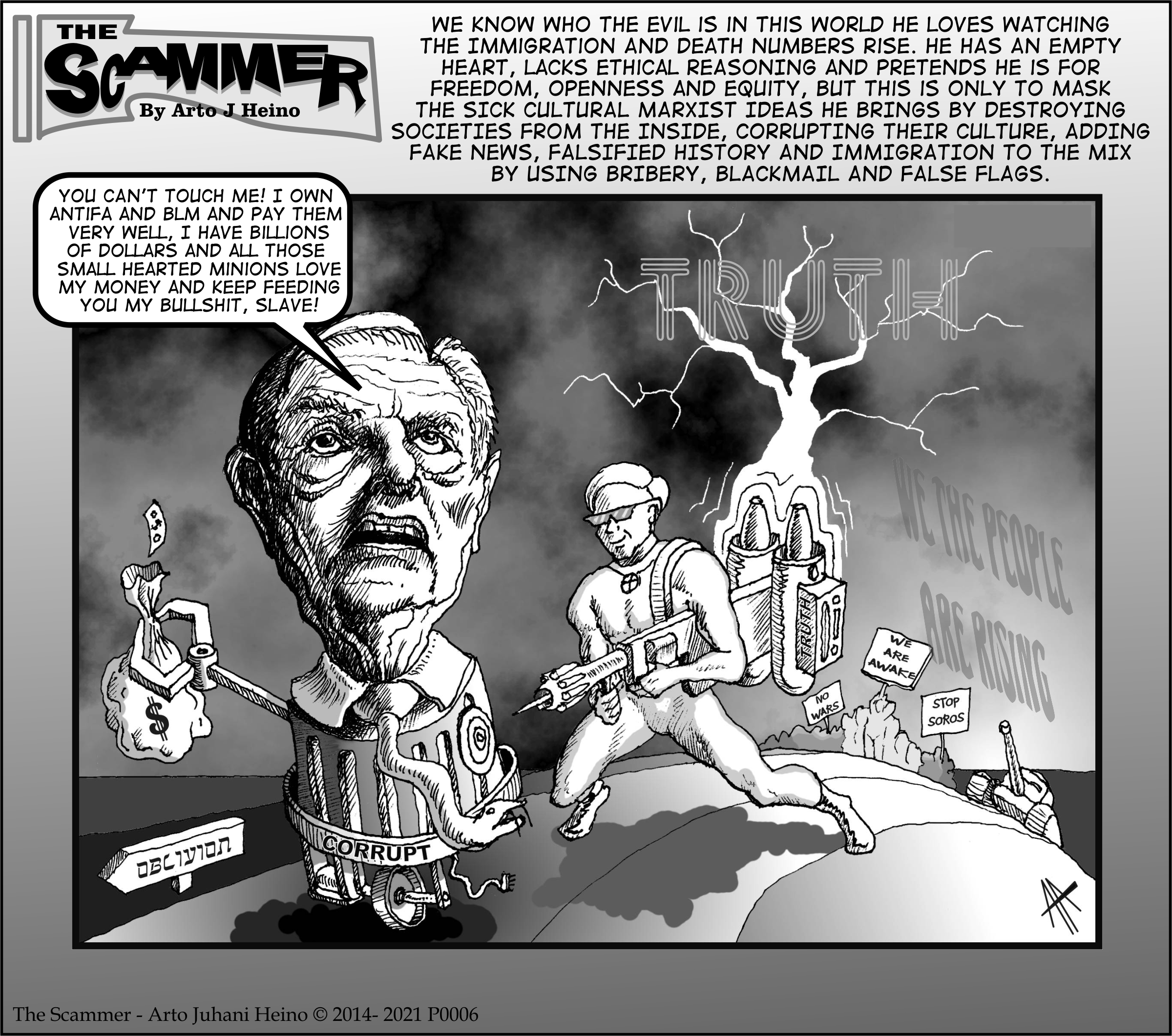
The Big Money Scammers
We know his name as the “Gate” keeper, he directed Microsoft to be an insecure and bug ridden operating system, easily to disable and infiltrate, allowing outside hackers to steal and damage your computer. Who are these hackers, a small percentage are hard core criminals, where the large proportion are really the Cabal itself hiring actors and proxies to do their will, dirty Soros money plays an indirect role here. The University trained Marxists have computer skills, they watch Dystopian movies and read Dystopian Comics, the “Woke” clothing companies created clothing fashion to coincide with this vision, to add to the mix, “Zombies” became the thematic material for pop culture for the last 10 years. The Cultural Marxists took over the Arts long ago, it was not as blatant in its opposition to Family and Nationhood as it has been now when we can easily see when “Woke” is written into the script, Ad or Comic. The Cabal decided that poisoning the public in multiple ways was just what they need to do, in out tastes, smells, thinking, movies, books, art, music, medicine and food, so chaos rules our lives.

So we can see the “Smirk” written on Bills G’s face, he is hiding a false reality that he help nurture, we all think a “Virus” is a thing that enter into your software via your hardware connection and starts to destroy it, so we buy “Virus Scanners” for this purpose. With the help of many Woke Professors and Gates himself, they equated Hardware with the brain and Software with the mind, the next step, with the help of Bill again was to equate Hardware as your body and Software as your DNA inside the cell, which was done successfully by a fraudulent science call “Virology”, promoted strongly by his partner in this criminal enterprise, Mr Fauci. The so called “Virus” would enter your body via touch, mouth and breathing and destroy your cells by entering it, causing disease and you would die, this is the discredited “Germ Theory”, your body would have to deal with it, so a Vax would be like a “Virus Scanner” that would help fight it and destroy it. They even said they added extra “Stuff” to it to make it even better, an “Upgrade” on the standard model, they would upgrade your DNA, using mRNA technology, a distraction as Graphene Oxide is the main killer, it acts like nano sized razor blades inside your blood system. The idea of prevention and health safety is the mental rubbish they filled the leftist “Woke” minds, while destroying any critical thinking skills along the way, still, they usually wake up from the psychosis after they are in hospital suffering from thrombosis.

We need to celebrate Poland, as they have begun the Nuremberg Trials 2.0, against all those who are creating such chaos, murder and suffering in the lives of humanity. At the same time the EU are trying to nullify and cancel the “Nuremberg Code”, the same code they wrote to vilify Germany after they lost the war, on perceived and imagined crimes, now it is coming back to destroy them.
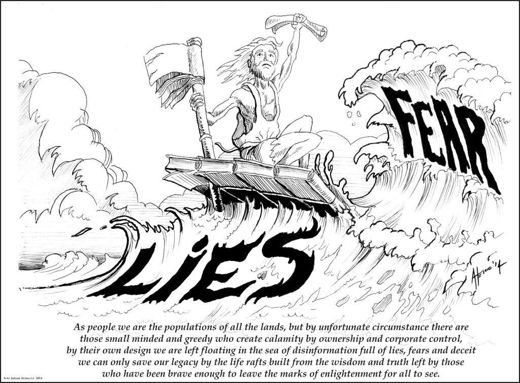
Just so my reader understands, this criminal cabal was clearly understood in my ode from a previous post in 2014.
I thank my readers for their support, regards Arto.
Make a one-time donation
Make a monthly donation
Make a yearly donation
Choose an amount
Or enter a custom amount
Your contribution is appreciated.
Your contribution is appreciated.
Your contribution is appreciated.