Here are some more Synthonyms, Enjoy.
Synthonyms II
August 31, 2012Multi-Filar Coils
August 24, 2012While making observations of coil designs that have been used over the centuries, I noticed only those that showed some perceived useful results were kept in the arsenal of the scientists, the rest were either ignored or forgotten. There are two basic types and a 3rd being the combination:
1 Circular – Eg Solenoid, flat spiral,spherical, toroidal, mobius
2 Non-circular – Eg Basket weave, geometric, polyhedral, star forms, mobius
The circular types have 3 basic types a resultant 4th and the unique 5th type:
1 Rings adding vertically – Solenoid Coil
2 Rings expanding diametrically – Flat spiral
3 Rings adding in a circular form – Toroidal
4 Rings adding vertically and/or diametrically and/or circular
a) Conical – differing sizes in both direction
b) Multilayer Solenoid – same sizes vertically + differing sizes diametrically
c) Multilayer Flat Spiral – same coils sizes vertically + adding vertically
d) Toroidal and Poloidal windings mixed sizes vertically + differing sizes diametrically
e) Spherical rotations windings mixed sizes radially + differing sizes diametrically
5 Winding folding into itself, creating a single surface – all possible geometries – Mobuis
The shapes of coils are one aspect the other is the winding order and direction, thus creating multiple poles, cross coupling inductance, retarding or increasing both the inductance and the capacitance as the design requires, the addition of the mobius windings diversifies the basic options, this is where the art is at in 2012. A good example of combining many geometries and winding types is the:
Magnetic coil(1820 Hans Christian Oersted)
Faraday coil(1831 Micheal Faraday)
Henry coil(1831 Joesph Henry)
Induction coil(1836 Nickolas Callan)
Ruhmkorff coil(1851 Heinrich Ruhmkorff)
Helmholtz coil(1869 Herman von Helmholtz)
Maxwell coil(1873 James Maxwell)
Cook coil(1871 Daniel Cook)
Tesla coil 1/4 wave(1891 Nicola Tesla)
Tesla Flat coil(1890 Nicola Tesla)
Tesla Bifilar coil(1894 Nicola Tesla)
Hubbard coil(1918 Alfred Hubbard)
O’Leary Coil(1920 William O’Leary)
Hendershot coil(1928 Lester Hendershot)
Interceptor coil(1946 John Wiegand)
Tokamak coil(1950 Oleg Lavrentiev)
Stellartator coil(1950 Lyman Spitzer)
Smith coil(1952 Wilber Smith)
Fusor coil(1964 Philo Farnsworth)
Hooper coil(1968 William Hooper)
Rodin coil(1986 Marco Rodin)
Biaxial Poloid coil(1990 Bo Atkinson)
Tetra Helix coil(1991 Bo Atkinson)
Vortex coil(1992 Ken Gailey)
Double Helix coil(TM) (2007 AML)
Not to mention my own explorations in coil geometry with:
Mandela coil(1990 Arto Heino) – Page 55 – Link
Crown coil(1994/2011 Arto Heino) – Link
Infinty coil(1993/2011 Arto Heino) – Link
– and many toroidal/polyhedral mixtures that have been popping up regularly with names like the Star ship coil, Loohan coil, Polish coil, Big Secret coil, some of these are marvels of artistry and human innovation.
Not to mention the many non inductive windings that are used as resistances. This has been looked at for at least 200 years, Nicola Tesla was one engineer/Scientist who’s original thinking left a legacy of numerous winding geometries he used to design his motors and coils,one of these is his Bifilar design. This design exposed a unique addition to the idea of combining the merits of both coil and capacitor without addition hardware contrivances, the anti-series winding nulls out self-inductance.
Nicola Tesla writes that a standard coil of 1000 turns with a potential of 100 volts across it will have a difference of 0.1 volt between turns.
100/1000 = 0.1
A similar bifilar coil will have a potential of 50 volts between turns.
100/2 = 50
In that the stored energy is a function of the square of the voltages, the ratio of energy in the bifilar to a standard coil will be
50^2/0.1^2 = 2500/0.01 = 250000
Which as stated by Tesla, “the energy stored is 250000 times greater than the standard coil!”
The storage of energy when pulsing a bifilar coil is n amount more than a standard solenoid/flat coil, as Tesla stated and gave you the formula to engineer this type of coil, we should be incorporating this simple idea into many everyday devices. I have drawn a few design methodologies that I hope will spur this well known innovation into more interesting directions.


These are basic bifilar solenoid configuration showing the capacitance between each winding. The windings can be rearranged in a different order to change the amount of induction and capacitance you put into the coil. The winding below shows what can be done to rearrange the capacitive differential to increase the energy storage.

The graphic table below shows how many different arrangements that can be used with a Quadrifilar coil system, each will give a different result for the inductance, capacitance and its resonant frequency spectrum.
A great science/engineering project or University paper for someone would be to tabulate and analyze each arrangement, you might just get your doctorate on this.

The flat coil is a dimension less than the solenoid and a lot easier to redefine into multi-filar arrangements.

The basic geometries involved in designing coils, transformers and bifilar systems must have a few design rules so the engineering of these items become straight forward and adaptable to the needs of the energy transformations. Here are a few simple systems that can be easily expanded and used creatively.

The cipher I am using here is:
B = Blue R = Red
U = Upper L = Lower
N = North S = South / is the upper part of the cross
E = East W = West \ is the upper part of the cross
The order of the letters is the order from the top to the bottom.
The order of the numbers is from the left to the right.
The first set is based on 2 simple loops. This will give you 8 different forms:

The next is the topology of a single loop of wire which loops on itself, like a bifilar or just a plain solenoid:

As you can see by these configurations, the standard engineering practice used in industry only use a small portion of these geometries. Now if you loop 2 coils as used in transformers you will see industry only apply 1 or 2 of these geometries in 98% of all transformers.

The fusing of Adams motor and the Tesla bifilar coil was one of the first iterations that showed me the correctness of this approach by its exceptional efficiency.

Incorporating both bifilar and loop transformations as shown previously, you can begin to appreciate the transformations I have below to create a magic square coil, as originally shown on my Artoworld website in 1999.

Old photo from 1999

Most of the original readers of these documents never understood my topology in 1999, even though I built many of these coil constructs as stators for pulsed motors. The current breed of experimenter has less inhibitions to these geometric forms. The first arrangement is the non-magic numeric sequence, just the same as if you wrap a standard solenoid.


The next diagram is the magic square arrangement, which utilizes the the pairing of the “17” as a magic square paring which translates to the bifilar pairing.

Below is the original stator coil I wound in 1999, it performed well and required high voltage(24v) and low current(0.001 amp).


I hope this small extract from my upcoming book “Talking with the Birds” will be helpful in any research you might be doing. Regards Arto
Here is Link to a Multifilar Coil Manufacturer, called Custom Wire Technologies Inc. Give them a buzz they might help you, Regards Arto
*** Update***
I have had a request to explain the Tesla/Adams Bifilar setup, here is a diagram that should make it transparent. The consequence of using this way of connecting coils will give you a multitude of possibilities for the experimenter to find interesting combinations , have fun regards Arto.
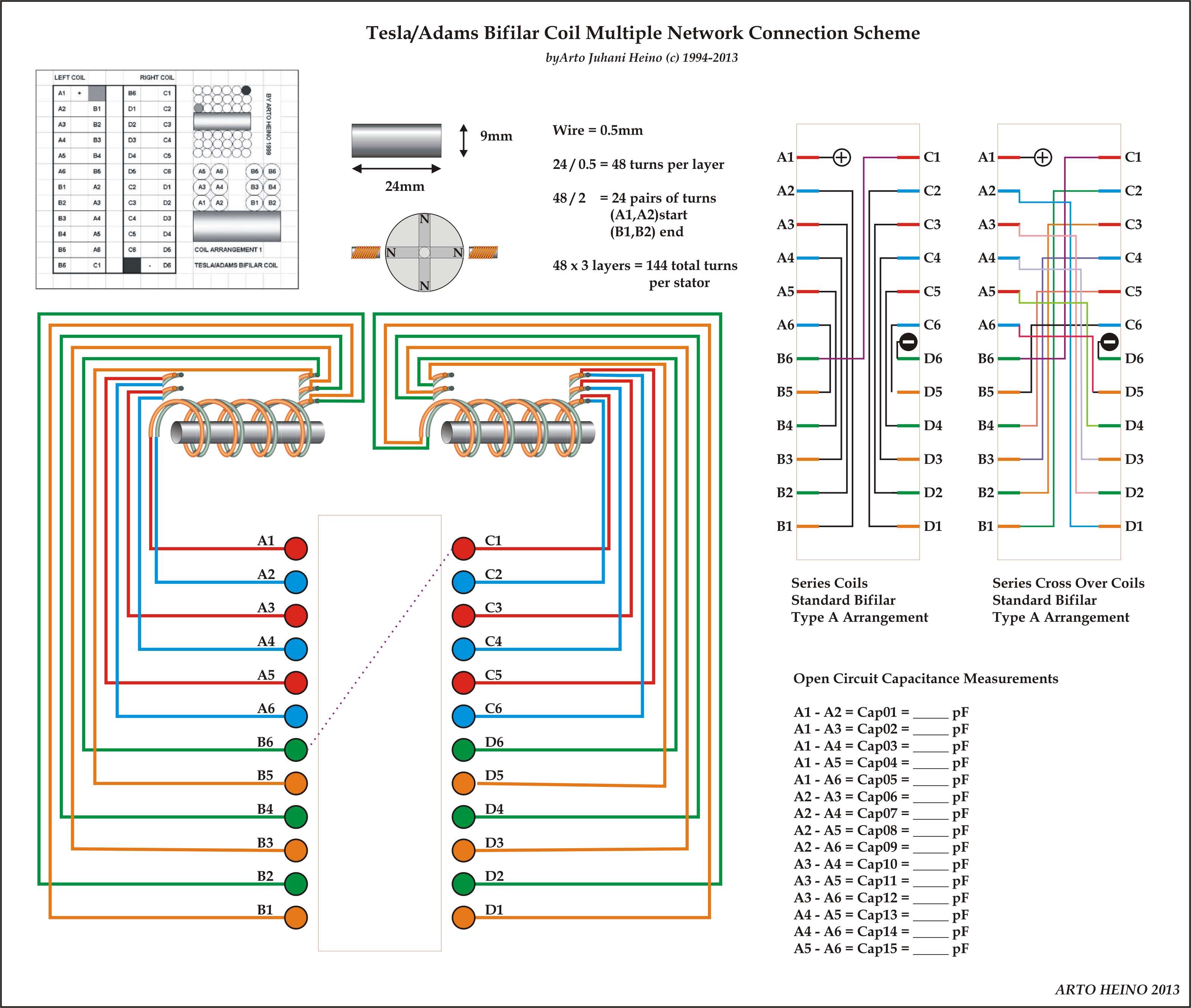 *** Update 2 *** 03-06-2013
Thanks to Andy I have added one more diagram to help decipher my Magic Square Coil arrangements.

*** Update ***
Added the Spiral coil implementation.
 For the continuation of this blog go to : https://artojh.wordpress.com/2013/06/05/magic-square-coil-technology/
Or buy my book at Amazon.com
One-Time
Monthly
Yearly
If you would like to help my efforts in all my future posts, I would very much appreciate your donation.
Make a monthly donation
Make a yearly donation
Choose an amount
¤5.00
¤15.00
¤100.00
¤5.00
¤15.00
¤100.00
¤5.00
¤15.00
¤100.00
Or enter a custom amount
¤
Your contribution is appreciated.
Your contribution is appreciated.
Your contribution is appreciated.
DonateDonate monthlyDonate yearlyThe Infinity Coil
August 4, 2012When I was working on the many forms of the Robert Adams motor in the 1990’s , I was happy to fulfill the basic tenants of the original Robert Adams design. The clear revelations of a simple switched reluctance motor with parametric amplification factors that can go into resonance with itself and the larger environment gave me inspiration in the form of a double coil in the figure eight with two rotors running in opposite directions and two sets of pulse coils.

After many years I decided to return back to these designs as they merit greater experimentation. The original Infinity coils were two solenoids in parallel wound in a figure eight fashion, this would also work on two toroids stacked in parallel also adding the bifilar winding scheme, this became my final design as shown below.


As to the functionality of this coil, I put together a simple pulse circuit, that only uses a 0.5-3volt source and lights a MR16 3W light for about 10 hours beginning at 60% illumination, as shown below.

There is still more work that has been done on this arrangement as all relevant factors are notated in my up coming book ( “Talking with the Birds”) and have been explored to a greater degree than presented here. Regards Arto
Longitudinal Sonics
July 22, 2012If you really want to understand how longitudinal waves can be transmitted, received and created through a medium you cannot be happier than discovering the work of George Constantinesco. He was a Romanian inventor who gave us a lasting legacy “The Theory of Sonics”, a new (in 1913) science of power transmission though Solids, Liquids and Gases. The same understanding of Teslas longitudinal electric wave can be engineered using Contantinescos mathematics and understanding. I have drawn a diagram of a possible impusle system of transmission, based on one of his patents, this could be built and replace a gearbox, drive shaft and differential from a vehicle. This is only a small design model for experimental purposes, so good luck and have fun if you choose to build it. Regards Arto

Synthonyms
July 17, 2012Here are a few of my recent play on words or as I call them “Synthonyms”, enjoy regards Arto


The Tesla Crown Coil
July 13, 2012Back in 1994 when I was working on my Mandela Coil which the forums currently call the Starship Coil, I needed to isolate the resonant action of the top load and the third coil, this led me to designing the Crown Coil. On paper the Crown coil was promising, it was only after building one of the versions of the Crown coil in 2011 that I was pleasantly surprised on how well it performed.

I hope these pictures help you make a version of this coil, just remember ***the outer vertical winding’s end at the tube*** each one joins to the spiral coil at the top and at the bottom, they do not go through the center of the tube as per the diagrammatic picture above.
As all the researchers in the forums and Tesla groups are discovering the inductive action of a Tesla secondary will encompass the tertiary coil, unless it becomes decoupled from it. Using a sphere as a top load will not be enough, a toroid will allow this differentiation and decouple so it can drive another load without affecting the impedance of the secondary. The Crown Coil also acts like a toroid and a tertiary coil in one.

This is an experimental design and could be vastly improved given the right recourses. all the data is preliminary and not complete. If you choose to copy this design please give due credit, regards Arto.
The coils inductance values are in series for six strands and paralleled for two groups. The capacitances are a lot harder to define and I have only presented the tentative values I gathered from measurements.
L1 = La1+Lb1+Lc1+Ld1+Le1 = 3.5776 uH = L2,L3….L12
L16 = L1+L2+L3+L4+L5+L6 = 21.4656 uH
L712= L7+L8+L9+L10+L11+L12 = 21.4656 uH
L16 + L712 = 42.9311 uH
Inductance in parallel L16 and L712 = (L16 x L712)/(L16 + L712)
L = 10.7328 uH
C1 = Ca1+Cb1+Cc1+Cd1 = 2.975 + 8 + (2*((1/220)x6))/12 + 8 = 25.09 pF = C2.C3…C12
C = C1 *12 = 301.03 pF Capacitance in parallel
Note: Cc1+Cc2.+Cc3+Cc4+Cc5+Cc6 = 1 / ((1/220) x 6) = 37.66 pF Capacitance in series


Using an Oscilloscope and a signal generator I found the resonant frequency to be 2.8 Mhz very close to my calculations, I also found lots of harmonics above and below 2.8 Mhz
0.7 *
1.4 ****
2.8 ********** Octave 0
4.2 *
5.6 **** Octave 1
7.0 **
8.4 ***
11.2 *** Octave 2
22.4 *** Octave 3
As you can see by the list the electrical resonant notes are easily seen when sweeping the frequencies on my signal generator. The octaves are pronounced and a few other notes are also seen.
2.8 Fundamental
4.2 5th
5.6 1 st Octave
7.0 Oct + 3rd
8.4 Oct + 5th
11.2 2nd Octave
22.4 3rd Octave
I connected the Crown coil on top of my experimental Tesla coil secondary and ran it at 220Khz(1/4wave), it improved the spark length by 100%. This frequency was not concordant to the Crown coil, still it did show me I was doing something right.
After re-tuning the primary coil to run at 345Khz (pi/2 * Clight) , normally a Tesla coil will not work properly if the frequencies of the primary and the ¼ wave secondary are not set correctly. I was stunned that it worked and with a vast improvement of the system. Not only was the Crown coil getting pumped at a lower Octave = 2.8Mhz/ 8 , the coil was running at a super-luminal velocity!
Clight = Velocity of light = 299792458 mtrs per sec
Clight * pi/2 = 470912891 mtr per sec
Normal frequency of coil = 220000 Hz as per ¼ wave resonant Tesla coil
Additional frequency of coil = 345575 Hz as pi/2 x light velocity
After months of testing the crown coil in different situations, I decided to put a aluminum leaf electroscope on top of the Crown coil. This was an interesting experiment, as I observed the aluminum strips pulsating at about 0.25 Hz , I filmed this , but the quality was not clear(rushed arrangement), I will still post it.. An observer walked into the room had noted he felt a pulsing force as he walked towards the coil. I will conclude this a electrostatic pulse just as Tesla described in one of his arrangements. The driving system of my Tesla coil works nicely at about 100 watts (Variac 160 v * 0.625 amp)(NST 8000 v x 0.0125 amp), producing 150mm streamers, for hours if required. I have pushed the system to 400-500mm ungrounded streamers, but I found this unnecessary for experimental work, as things will start to fail if I run it for long periods.
As this is only the beginning of another journey of discovery, I am glad to share this with all who will follow the progress. The evolution of this coil will be interesting as the intensity of the charge increases as I tune the system, so as I redesign the Crown coil to resonate at different frequencies the tuning will become less critical. I will be eventually make to order a Crown coil to suite any Tesla Top load/ Third coil combination.
Adding other components to the crown coil such as a parabolic dish will make for some interesting experiments. I could direct the high voltage electrostatic pulses at any give direction. I have been carefully crafting the mold for it, the first few are very successful as Satellite dishes, Audio focus and radio astronomy projects. The parabolic dish is called the “The RAT Antenna” , this is a 600mm spun aluminum dish that is available for purchase from me, just email your inquiry, I will only ship in Australia.

This work here will be in my second volume of “Talking to the Birds”, the first volume is available now.
Tesla’s Patent Revealed
May 29, 2012TESLA PATENT 583,953
APPARATUS FOR PRODUCING CURRENTS OF HIGH FREQUENCY.
As quoted by Tesla in this patent, “In the description of the invention is designed for converting a continuous or direct current into one of high frequency.” , this can be interpreted as using 120/240 AC to Battery/Rectified as the electrical power source.
This part is describing how he uses a large induction coil and a rotary commutator for his switching circuits to create his pulsed energy, “I have employed a circuit of high self-induction connected with the mains from a suitable source of current and containing some form of circuit-controller for periodically interrupting it.”
The following is very important as Tesla only used a commutator to switch and didn’t use the modern equivalents such as transistors and diodes.“Around the break or point of interruption I have arranged a condenser, into which the circuit discharges when interrupted, and this condenser is in turn made to discharge through a circuit containing the primary of a transformer, and of such character that the condenser-discharge will be in the form of an extremely rapid succession of impulses.”
This part is the essence of his genius, by charging in parallel and discharging in series, Tesla increases the voltage potential available, “I subdivide the condenser necessary for storing the energy required into integral parts or provide independent condensers, and employ means for charging said condensers in multiple and discharging them in series through the primary of the transformer.”
The items F F are self-induction coils placed beside the motor. Above these is the transformer, composed, essentially, of primaries G1 and G2 and a secondary H.
L L designate the mains, between which a circuit is formed, including the self-induction coils F F and the commutator. The switch d may be employed to bring either or both of the coils F F into this circuit.
The commutator is built up of insulated plates or segments, upon which the positive and negative brushes bear, and these plates may be considered as belonging to three sets or classes:
1 – the plates m for what may be considered as the positive brushes D D1 in one row, electrically connected together, and the corresponding plates n for what may similarly be considered as the negative brushes E E1 in the other row.
2 – the plates o, which lie in both rows, and hence are conveniently made in single pieces extending across the controller.
3 – the idle or spacing plates p q, which are interposed in each row between the other two sets.
The brush D of one set is connected with one main through the coils F, and each one of the brushes of the same set is connected to one of the terminals of the condensers M N, respectively. Similarly the brush E of the other set of brushes is connected to the opposite main and each of the brushes of said set to the opposite condenser terminals through the primary or strands of a primary G1 or G2.
In the position of the parts shown in which two positive and two negative brushes are shown, the brushes are bearing on plates m m and n n. Consequently the circuit through the coils F F is through the condensers in multiple, and assuming that energy has been stored in said coils, the condensers will thus be charged.
If now by the movement of the commutator plates or brushes the latter are shifted across the idle or spacing plates p q onto the long or cross-connected plates o two results follow:
1 – The mains are short-circuited through the coils F F, which therefore store energy, while the condensers are connected in series through the primary coils G0 or G1.
2 – The condensers being charged in parallel when the brushes are on plates m n and discharged in series when the brushes pass onto plates o.
Diagram 1 – I redrew the main patent for clarity
Diagram 2 – These are the basic 3 action as the brushes change the configuration.
Diagram 3 – The Commutator schematic
Diagram 4 – How the Commutator is set up in 3D at the end of the motor.
I hope this helps in the understanding of Tesla’s methods used to create high frequency and high voltages without transistors, diodes or tubes.


Meeting Joe Satriani in 2005
February 9, 2012After a bit of a clean up, my daughter found the pic of our visit to Allans Music in Sydney on Monday 14th of March 2005, between 2 to 4pm. Here we lined up for 2 hours and were the LAST to be allowed to meet Joe. There was almost a riot that broke out behind me. It went something like this; Hi Joe I love your stuff, my daughter is a keyboard player who lists you as one of her favorite and most influential musicians. My daughter spoke to him and was very pleased to meet her, I sensed they had a mutual understanding. He was softly spoken and he showed his gentle and kind manner. Joe Satriani is a true Artist of his music and the guitar, we could all learn from his mastery of his instrument and his spirit.

Joe Satriani and my Daughter and Me
Oxford Falls Art Day
January 29, 2012A great day at Oxford Falls, Adam and I painted the local scenery and captured the feel of the day. I was a little sick from some bad yogurt the day before, but I was happy to keep the day positive till the end.

Urban Chalk Art – great time
October 10, 2011The rain came down on Saturday and most of the artists moved their work into Parramatta Town Hall, thanks for a generous and understanding council. I know the interior lighting changes your colour perceptions, we all tried to compensate for the slight change. We battled on until about 6.00pm. Here is my work at the end of the day.

Time 5.54 Saturday
Now the BIG day Sunday, here is my work at the 1.00pm deadline.

Final Chalk
The judging was straight forward, the presentation in the theater was great, they showed all the winners artwork on the main screen. I was pleasantly surprised by getting the ISS Security Guards choice award (Yay!!!), all the details of the event I will refer to the official website –
http://www.chalkurbanart.com/chalk-art-competition/index.html
