When you are designing binary circuits you will need to display your results in Decimal so it readable by the user, such as Temperature, Distance and Arithmetic calculation results. There are 74LS chips that will make the conversion for you, such as the 74LS148. It seems like we need to investigate the Ternary version and see if reveals some interesting results.
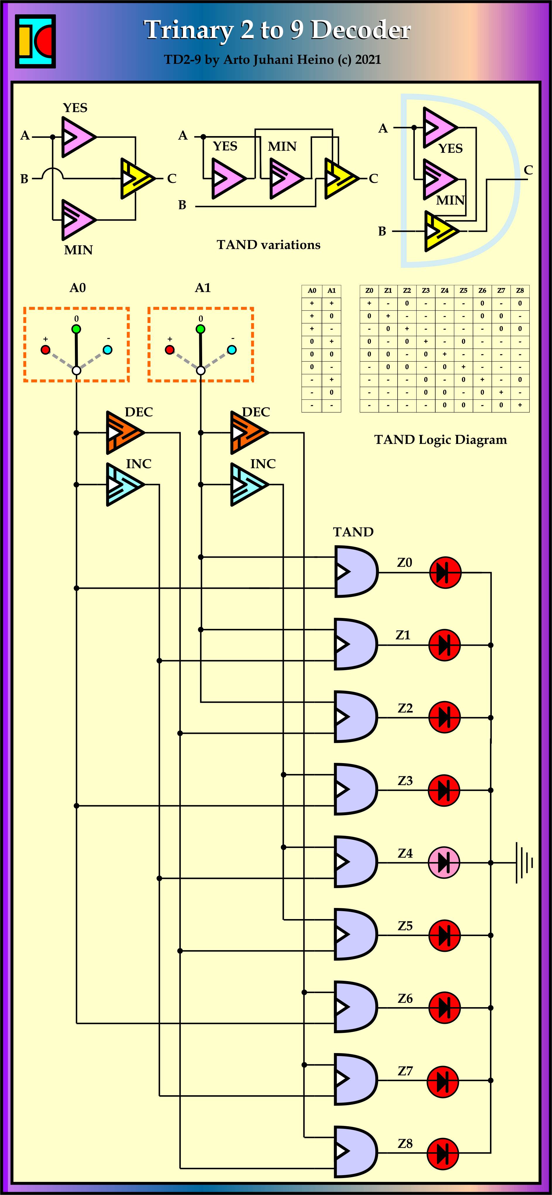
1A

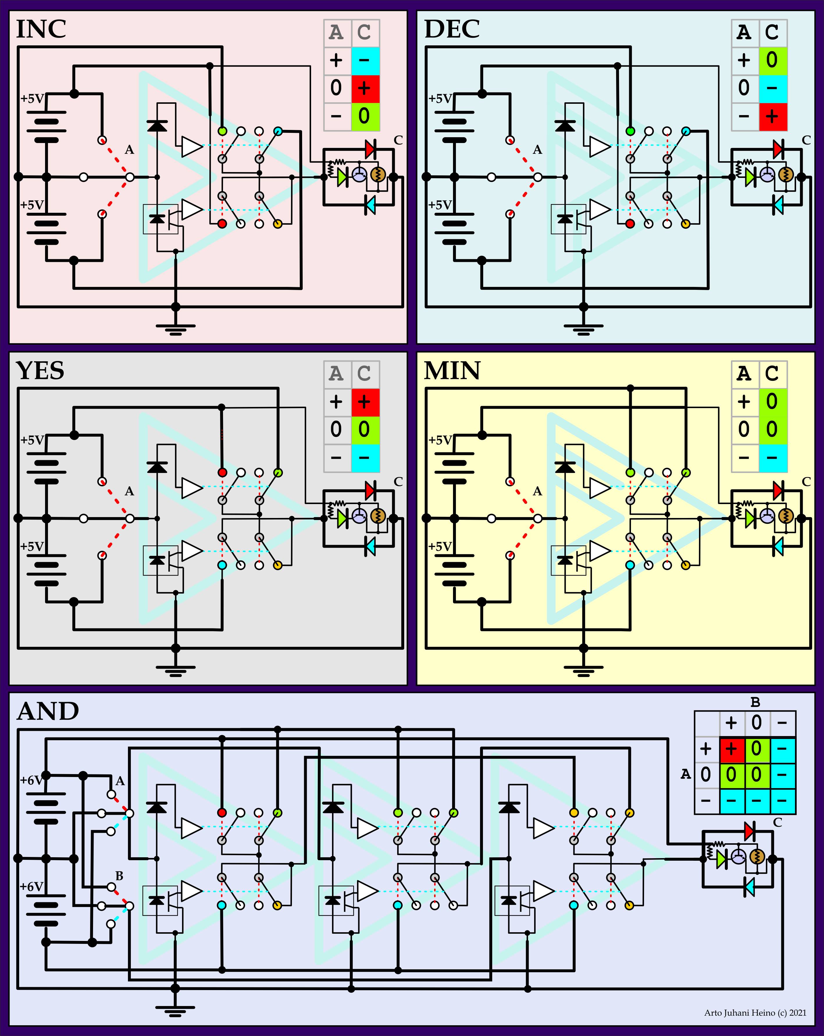
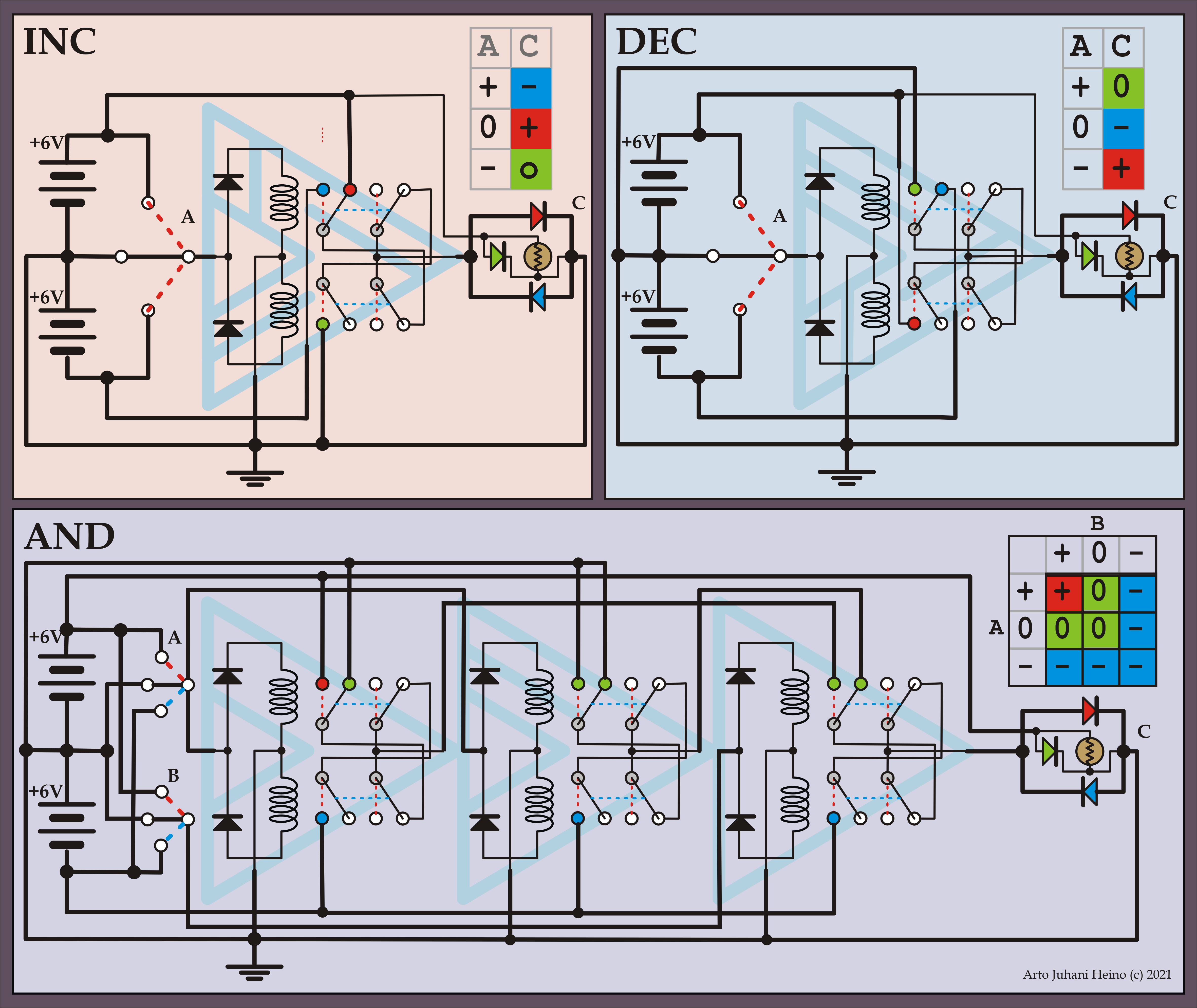
The first design (1A) utilises the well known Ternary TAND Gate, where the assertions are the positive voltage only.
1B

The second design (1B) replaces the TAND with a TONLY Gate as we have no need of the negative values if we are interfacing a binary circuit. Looking at the TONLY Gate it seems that we do not need such a complex gate as the ones used, maybe we could just use some Unary Gates to do the same job.
1C

Design (1C) fulfils this completely using only 3 Unary gates, by creating a USR Gate that can be modified by another input, in this case it is the positive that gets asserted from the result of the first input, the final Gate is just another cascade from the second Gate. The output is either positive or zero so it can be linked to a Binary circuit.
1D

The last design (1D) in this set reduces the Unary Gates to 2, thus allowing a negative as an output, this is mainly for use in other Ternary circuits, like the one I will show in another design (2B).
My basic approach to using Ternary, is to make it more useful than binary which has many short falls that nobody can see unless you have been involved in designing these circuits from scratch, the current pardigm requires a complex binary arch to acomplish results and requiring multiple iterations to arrive at a result. Where Ternary can accomplish more in less gate interations than binary. Each Ternary Gate is only slightly more complex than its Binary counterpart, such as the inverter.
These circuits show how much can be achieved with less resources while being less complex connections than the binary version.
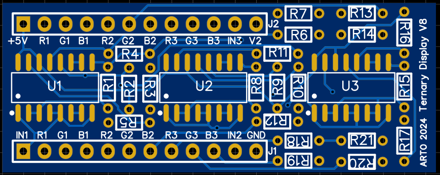
7 Segment Circuit
The final section is the Ternary to 7 Segment circuit. The first circuit (2A) is a basic 0 to 9 Led from a 3 Trit input, using the 3 Unary Gate logic from my earlier design (1C), the second circuit (2B) gives you another 9 more selections. Ternary easily uses negative numbers to increase data width selection, more elaborate schemes could be accomplished, like a complete 27 symbol choice, if I used all 13 positive numbers and all 13 negative numbers and zero.
2A
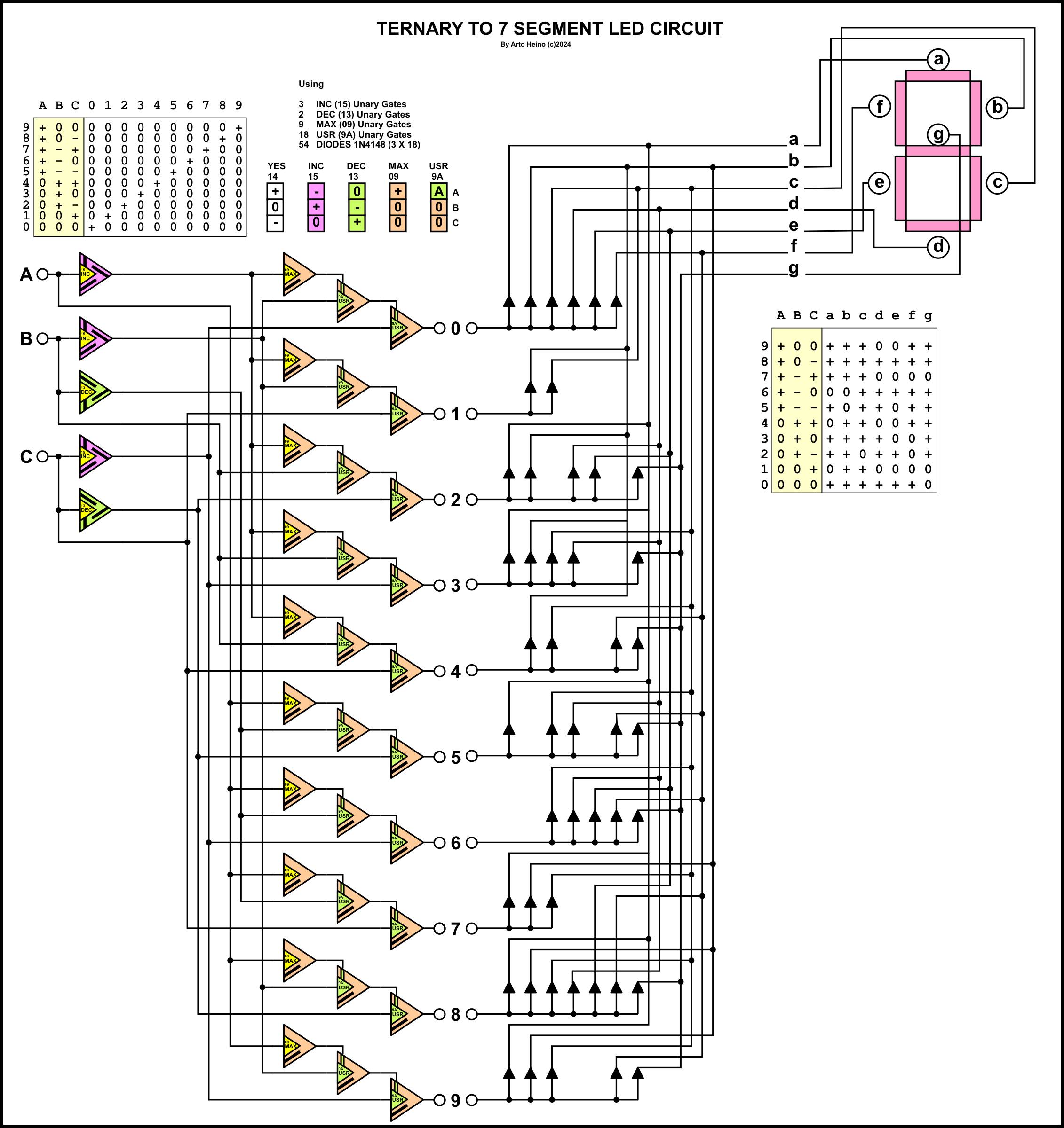
2B

Both of these designs use Diodes to accomplish the 7 Segment interface, making it suitable for a LED chip such as a Common Cathode TOS5121AR (Titan), LSD505400 (PlusOPTO), LTS-5003AWC (LITEON). You could even make your own with Leds or use a Large display.
I hope to finish my Division section of my Ternary ALU very soon, so far I have Addition, Subtraction, Multiply and a few Logic gates. I am still designing the shift registers and memory, while the ROM will be programmable with switches, I am basing it on 81 Trits at present.
Regards Arto