This article is from Popular Science Monthly, what a great read, and a very concise look at what the current developments were at the time, be it the theories or practical applications this article will be most interesting.

Popular Science Monthly
JULY 1917
SUMNER N. BLOSSQM Editor
VOL III. No 1
Wireless Power——The Next Great Invention
Electrical Experts, in Amazing Experiments, Reveal How Radio Beams Soon May Light and Heat Our Homes
By ALDEN P. ARMAGNAC
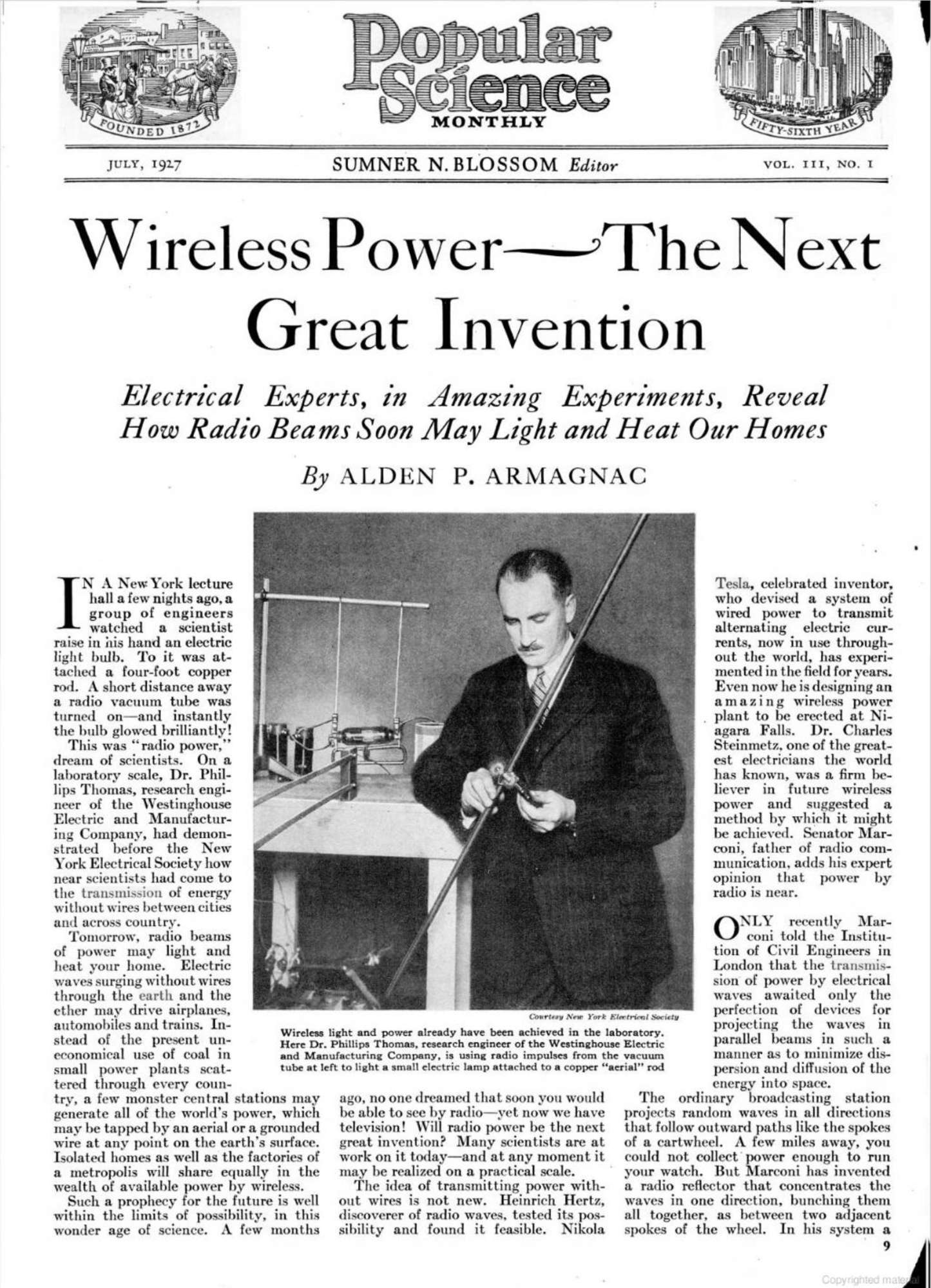
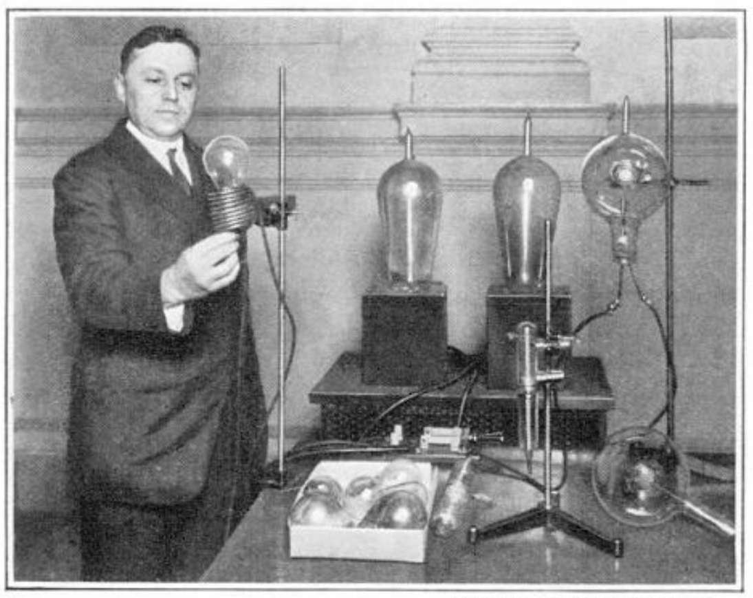
In a New York lecture hall a few nights ago. a group of engineers watched a scientist raise in his hand an electric light bulb. To it was attached a four-foot copper rod. A short distance away a radio vacuum tube was turned on—-and instantly the bulb glowed brilliantly!
This was “radio power,” dream of scientists. On a laboratory scale, Dr. Phillips Thomas, research engineer of the Westinghouse Electric and Manufacturing Company, had demonstrated before the New York Electrical Society how near scientists had come to the transmission of energy without wires between cities and across country.
Tomorrow, radio beams of power may light and heat your home. Electric waves surging without wires through the earth and the ether may drive airplanes, automobiles and trains. Instead of the present uneconomical use of coal in small power plants scattered through every country, a few monster central stations may generate all of the world’s power, which may he tapped by an aerial or a grounded wire at any point on the earth’s surface. Isolated homes as well as the factories of a metropolis will share equally in the wealth of available power by wireless. Such a prophecy for the future is well within the limits of possibility, in this wonder age of science. A few months ago. no one dreamed that soon you would be able to see by radio—-yet now we have television! Will radio power be the next great invention? Many scientists are at work on it today—and at any moment it may he realized on a practical scale. The idea of transmitting power with out wires is not new. Heinrich Hertz, discoverer of radio waves. tested its possibility and found it feasible. Nikola Tesla, celebrated inventor. Who devised a system of wired power to transmit alternating electric currents, now in use throughout the world, has experimented in the field for years. Even now he is designing an amazing wireless power plant to he erected at Niagara Falls. Dr. Charles Steinmetz. one of the greatest electricians the world has known, was a firm believer in future wireless power and suggested a method by which it might be achieved. Senator Marconi, father of radio communication adds his expert opinion that power by radio is near.
Only recently Marconi told the Institution of Civil Engineers in London that the transmission of power by electrical waves awaited only the perfection of devices for projecting the waves in parallel beams in such a manner as to minimize dispersion and diffusion of the energy into space.
The ordinary broadcasting station projects random waves in all directions that follow outward paths like the spokes of a cartwheel. A few miles away, you could not collect power enough to run your watch. But Marconi has invented a radio reflector that concentrates the waves in one direction, bunching them all together, as between two adjacent spokes of the wheel. In his system a number of short “aerials” are arranged in a curved row at the back of the main broadcasting antenna to reflect the waves it emits in a beam with parallel or at most slightly fan-shaped edges. Between London and Canada, and elsewhere. this type of “beam radio” has produced strong signals for radio telegraphy at a distance where ordinary signals would be weak and inaudible.
A “magnifying transmitter,” that hurls electric currents at millions of volts into the earth, to be recovered as power at any point on its surface, is the invention of Nikola Tesla. “The transmission of power without wires is not a theory or a mere possibility.” this wizard of electricity told me recently. “It is a fact which I myself have demonstrated in numerous practical experiments, conducted on a large scale with a generator of 1500 kilowatts capacity. As long ago as 1899 I found that the current from my magnifying transmitter traverses the globe and returns to its origin with undiminished strength. This at forded evidence that there was virtually no loss in the transmission through the earth: and that by a properly organized apparatus at the sending and receiving stations, power in industrial amounts could be transmitted with an efficiency as high as ninety-nine and a half percent.”
To TRANSMIT power through the earth, Dr. Tesla said, he plans to erect at Niagara a huge tower similar to the one he had partially completed on Long Island N. Y., when it was destroyed at the outbreak of the European war. Contrary to popular opinion, neither that nor the improved structure he proposes is a radio tower. Like some gigantic pile driver, it will jar the earth, not the air, with artificial thunderbolts manufactured in its mushroom like dome.
In the sky, as well as the earth, may lie the secret of wireless power. A study of huge sparks, some of them 400 feet long, that Tesla has produced in his laboratory, has shown that in the rarefied upper atmosphere electricity could travel with surprising ease, though at ground level it takes thousands of volts to produce a spark a few inches long.
Other experiments have shown that the levels at which such a low of electric power could be produced are within a reasonable distance of the earth,—say 30.000 feet above sea level. This has led Hugh Pollard, a British engineer, to suggest monster towers reaching into the clouds and topped by captive balloons, to feed power at millions of volts into the vast conducting layer of the upper air. At other points on the earth’s surface, such as Mount McKinley with its 20,000 foot peak in Alaska. Mount Whitney in California, and Mont Blane in France, similar towers would withdraw the power for distribution.
At the poles. Pollard points out, this conducting layer of air is probably much nearer, perhaps only a mile high, because here the rotating force of the whirling earth is little felt. and does not pull the atmosphere away from the surface, as it does at the equator. A polar power plant might therefore feed power more easily into the aerial electric reservoir. Moreover, the exploring parties of Vilhjalmur Stefansson and of Capt. Donald MacMillan in the Far North, and of Sir Ernest Shackleton, Roald Amundsen, and Capt. Robert F. Scott in Antarctic regions have reported that vast stores of coal, and occasionally oil, exist near the poles. There would be no lack of fuel, then, to run the plants—fuel that now lies unused simply because the cost of transporting it to civilization would be too great.
HOW well the theory of a low conducting air level at the poles agrees with fact is likely soon to be known. Arctic explorers invariably return with accounts of strange displays of northern lights—a weirdly beautiful electric phenomenon still not fully understood, but known to have a definite connection with the electrified upper air. The most recent polar expeditions have collected masses of scientific data taken from auroral observations, which may confirm the existence of such a low-hanging layer. The amazing system of wireless power proposed by Dr. Steinmetz, the exact opposite of Tesla’s “earth power,” was to girdle the earth with power from the outside instead of from within. A broadcasting station, he said, might emit a wave of tremendous strength—millions of horsepower—that would circle the earth and return to its starting point. If the wave length were properly chosen, such a wave would have lost only a small part of its power by the time it completed its journey, and would continue its circuit many times. The broadcasting station would time its successive waves so accurately that the first one returned at the exact moment that a similar one was being sent out. The only additional power required. then, to keep the waves going would be to make up the slight loss in transmission, as long as no power was being withdrawn. When some receiving station “tuned-in” to withdraw the wireless power, it would “leave a hole in the wave” that the broadcasting station would make up by supplying an additional amount. Many stations scattered over the world could feed power into the wave, each one carefully timed to emit its waves just as the main wave passed by.
“Radio power” of another sort was used by Dr. Harvey C. Rentschler, like Dr. Thomas a Westinghouse research engineer, to perform a feat that had baffled chemists for years. He demonstrated his apparatus on the same night that Dr. Thomas disclosed his method of transmitting power without wires. In a new type of “radio furnace“ that melts metals in a vacuum. Dr. Rentschler succeeded in obtaining the rare metal uranium in a solid mass for the first time. The device that accomplished this remarkable result and thereby inaugurated a new science- “radio-chemistry ”—was designed to focus a large quantity of radio power in a small space, rather than transmit it to a distance.
When Dr. Rentschler threw a switch that turned on the current, radio waves from a powerful electric coil pierced the emptiness of the vacuum to generate a terrific electric current in a small capsule of impure powder containing uranium. There was a flash, and incandescent metal swelled to a molten mass. When it cooled, Dr. Rentschler was the first man in the world to see what this extremely heavy metal looked like. Much like iron in its grayish appearance, it was far more precious than platinum.
Other rare metals of like properties yielded their secrets to Dr. Rentschler when placed in the vacuum and heated by radio waves. The new furnace is of inestimable value to chemists, who can now watch reactions they could never see before that can take place only at high temperatures, in a vacuum.
With radio power in a test tube already achieved, will the next step be radio power in your home? Very likely, Dr. Thomas told the scientists who witnessed his demonstrations of lamp-lighting by radio.
Already he can transmit power without wires over a short distance. With improved vacuum tubes and electric circuits, he said, he hoped to improve his power transmission until he produced a type of wireless wave that would yield a space-annihilating beam over which huge quantities of power might be sent.
Short radio waves, ten thousand times shorter than those used in broadcasting, are the means Dr. Thomas will use. His goal is a “beam radio”—but a beam unlike any that has ever been produced. If he can make his radio waves short enough and powerful enough—he will focus them to a narrow, four-inch ray by means of a curved metal mirror!
Then he will project his beam, like a searchlight, to its destination. Such rays would criss-cross a city, and wires would become obsolete. Each home would have its own “rod receiver,” a short copper wire, resembling the one Dr. Thomas used in his demonstration, with which you could tap the power flowing through the ether just as you now listen-in to music with your radio set.
The idea of reflecting radio waves with mirrors may seem a little startling, but your own experience will yield the evidence in its favor. The silvered reflector of your car’s headlight concentrates its rays in a parallel beam. Light waves and radio waves are closely related to each other, differing only in their length; the waves of light are much shorter. Could radio waves, like light, be focused?
In between light and radio are heat waves—of medium length. Like light waves. they too can be obtained of short wave and maximum power. The radio wave that furnished the wireless current supply was only two and four-tenths meters—about eight feet long; yet through it he was able to “broadcast” thirty watts, about a twentieth of a horsepower. He can produce a wave of half that length, though his power is also cut in half.
To try out his scheme of reflecting a beam with a metal mirror, Dr. Thomas awaits the shorter-wave, higher-power beam he hopes to obtain. In his demonstration he allowed his radio waves to scatter at random through the surrounding air, and his feat of transmitting an appreciable amount of power was therefore the more remarkable.
DR THOMAS is not the first scientist to light lamps by radio; his simplified apparatus, rather than the demonstration of wireless light, is his greatest accomplishment. Nearly four years ago, Dr. Willis R. Whitney, of the General Electric Company, demonstrated before the American Association for the Advancement of Science at Cincinnati what he then characterized as an advance “as near to the wireless transmission of power as we have yet seen.” Standing a foot away from a powerful electric coil through which alternating current was pulsing at high frequency he held up a lamp bulb like those in your home and caused it to glow by wireless power. This experiment follows the same principle as Dr. Rentschler’s radio furnace, instead of Dr. Thomas’ method of using radio waves at a distance.
More than twenty years before, Nikola Tesla first lit a lamp by radio. He used a wave of a size that required a huge receiving coil of wire attached to the lamp. The other end of the coil was grounded, and the length of the wire was so chosen as to be exactly “in tune” with the broadcasting station hundreds of feet away.
What Dr. Thomas has done is to substitute for complicated receivers an ordinary piece of straight wire, made possible by the short wave he has produced. To pick up power from any radio wave, the rod, Dr. Thomas found, must be exactly half as long as the wave itself. Collecting current from a broadcasting wave would therefore require a rod of unwieldy length. With Dr. Thomas’ eight-foot wave, it need be only four feet long—a handy little rod to keep in your home!
The way that Dr. Thomas‘ “half-wave receiver,” as he calls it, picks up power from the air might be illustrated by placing a hollow tube half an “ocean wave length” long in the breakers at the seashore, pointing out to sea. One end of the tube would lie in the crest of an incoming wave. the other in the trough of the preceding one, and water would surge through it in one direction. A moment later, the crest would have reached the other end. the first end would be in a trough, and water would rush through it the other way. In the same manner an alternating surge of current runs back and forth along the metal rod from the radio waves in the air.
This much science already knows about the mechanics of generating and handling the radio power beam. But there will be more to learn— for the ray that Dr. Thomas seeks in his East Pittsburgh, laboratory, is a dangerous subject for experiment before scientists learn to control it. No one knows what might happen if such a beam were turned loose!
It might render the air through which it passed a conductor of electricity, much as does a bolt of lightning temporarily—and turn a shaft of air into an “electric wire” along which you could send an ordinary electric current. The radio beam, then, need not itself conduct the power, but serve simply as a channel for electricity.
For instance, an isolated mining camp in the face of an inaccessible mountain might receive electric power to run the mining machinery from a beam shot through the air from the base of the mountain.
One thing, Dr. Thomas says, is certain— with half the power of a modern broadcasting station behind it, a short-wave radio ray focused in a narrow beam of concentrated power would kill anyone who stepped in its way. Stray electric currents which it would induce in a man’s body would instantly burn him up. Here, then, is it veritable “death ray”—not a fantastic dream, Dr. Thomas points out, but like radio power a sober scientific possibility. In time of war, this ray would prove a terrible and awe-inspiring weapon. Radio rays of overwhelming power turned upon an enemy army would cause it to disappear in smoke. Along the radio beam might course powerful electric currents to complete the destruction.
BUT in its peacetime uses it would be of greatest service to man. High towers could be used to keep the deadly beam where it could do no harm as it transmitted vast quantities of power across the earth. At night a bluish glow would surround the transmitting tower from leakage of the high-tension current, and perhaps even the beam would glow like a searchlight piercing faint mist.
Smaller beams, less dangerous to man, might distribute the power at the receiving station. This would correspond roughly to the present system of using transformers to change the dangerous high-tension electric current used in wired power transmission into low pressure current safe for home use.
Into your home, perhaps straight through the wall, the ray would enter, while the “half-wave receiver” would absorb power to light your lamps—not ordinary lamps, but a special type of electric light built like a radio vacuum tube—and run your washing machine and electric toaster.
Can it be done? The “ifs” are merely matters of figures now. Scientists have taken away the mystery that cloaks radio power, and have shown how it is to be attained. Each by his own method, they are drawing nearer and nearer to its useful realization. With all the resources of great laboratories at their command, they are working out the last practical details. Any day, now, they may announce to a waiting world that at last the goal has been achieved.
 Courtesy of New York Electrical Society
Wireless light and power already have been achieved in the laboratory. Here Dr. Phillips Thomas, research engineer of the Westinghouse Electric and Manufacturing Company, is using radio impulse from the vacuum tube at left to light a small electric lamp attached to a copper “aerial” rod
 How radio eventually may supply our homes and industries with light, heat and power. Our artist pictures here his conception of a wonderful power transmission system of the future, based on present laboratory experiments. High power beams of short radio waves, projected for long distances by means of huge reflectors, would be tapped by receiving apparatus, much as we now tap broadcast radio programs.
 The famous power tower at Shoreham, Long island designed by Nikola Tesla to transmit thousands of horsepower through the earth. It was dismantled at the outbreak of the European war. The inventor now plans to construct a similar tower at Niagara Falls.

 Courtesy New York Electrical Society
A remarkable concentration of radio power. Dr. Harvey C. Rentschler, Westinghouse research engineer, demonstrates his new type of “radio furnace” which melts metals in a vacuum. Powerful radio waves from the electric coil above Doctor Rentschler’s hand penetrate the adjacent vacuum tube and generate a terrific current in the metal within.
* END *
Here are the original pages.