by Arto Juhani Heino (c) 2015
(This is still in a preliminary stage of writing for a chapter in my next Volume, please excuse any errors)
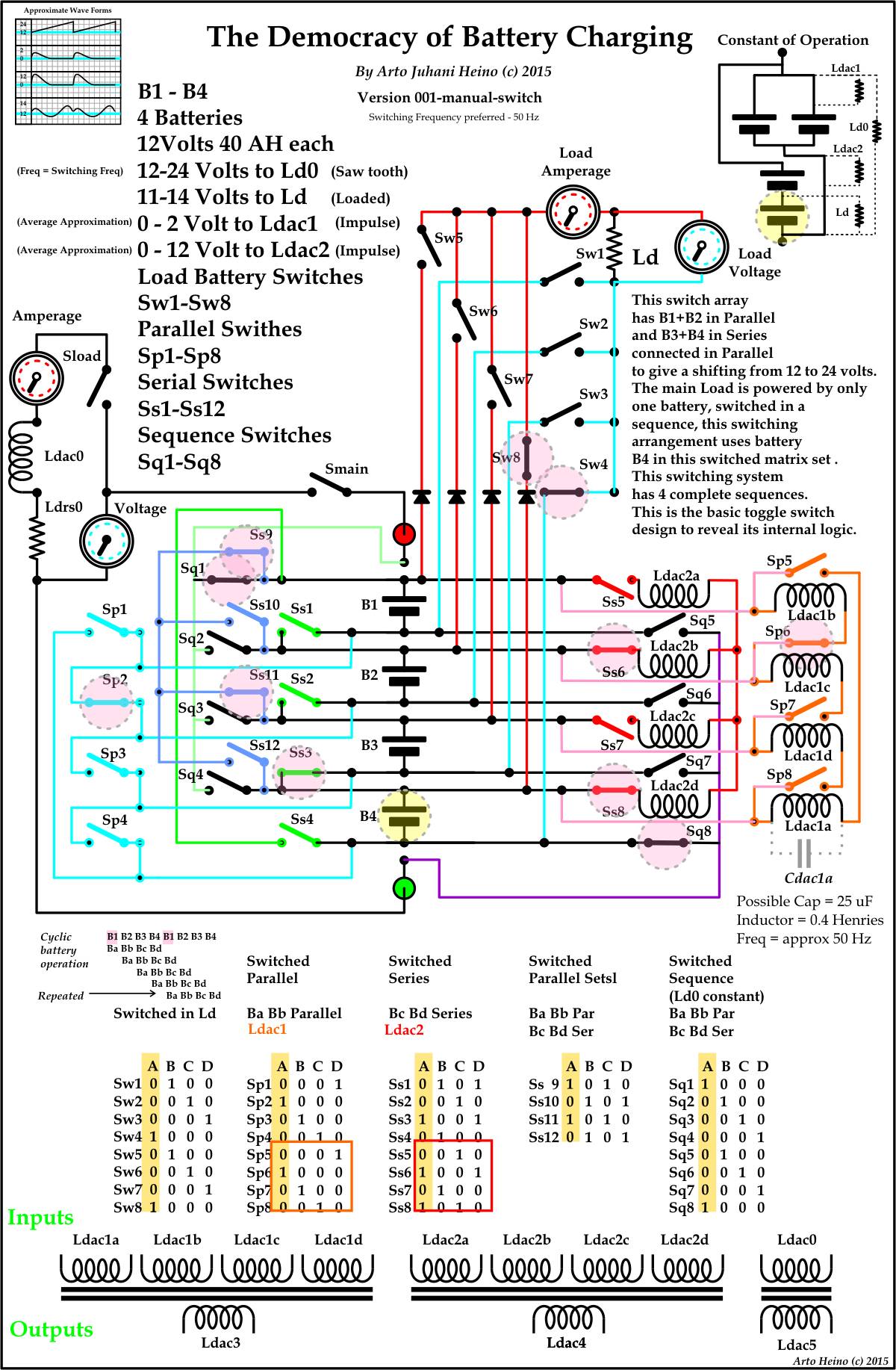
I originally chose to call it “The Battery Charging Switching Method (BCSM)”, but due to a clear reasoning I renamed it. Each battery in turn is used to power the load and all the differences between batteries are constantly harmonized and balanced while using the differences as outputs for creative applications. Now if we could only run a real government using these principals we really would have something happily called democracy, at the moment what they call democracy is a painted mask hiding the oligarchs who glean there riches from the public under the guise of true government. This is the same as using willing slaves to turn the cranks of generators to power the load of one single machine that return no excess power back to the prime movers energy stores, to help recharge them, just in case the prime movers decide to build up its own energy reserves and maybe divert any excess to improving efficiency and lower the cost of distribution, this is pure heresy to the pyramidal control structure.
I was fascinated by the announcement back in the 90’s of a Tesla Switch, I decided to investigate, I found no credible source for the name Tesla for this scheme anywhere, so I dismissed the title and looked at the circuit. First I noticed the whole scheme needed either a mechanical , rotary or electronic driving mechanism, so the switching had to use power to activate. Secondly I noticed the load connections had some problem with the simple fact that the use of polarized capacitors in a possible oscillating system, this was interesting as the load was connected to the negative rail on both capacitors. Ignoring these issues, I had to stretch my imagination to include differentials of polarizations on either side of the system might account for a charge pushing through the load. Yes I could see if you swapped the batteries from 12v single to 12v parallel you would develop a differential if either battery was not exactly equal in charge, this was the first inkling that this was not completely bogus.
I began analyzing this simple switching system and found this as my first breakdown.

It looks like the original switching scheme was meant to drive a load between two earth rails, as this is not a design that would be advantageous to the whole idea of recharging the batteries and drive a load, I would need to see if the charging battery idea is worthy of its implication as scheme of merit.
Here I have the switching idea of Benitiz, and I must say his understanding of this is worthy of his patent.

As you can witness, Benitiz’s idea that by a simply putting 2 batteries in series and 2 batteries in parallel is a way of increasing the voltage in the parallel set 12v with the higher 24v of the series set, where the amperage capability has increased with the parallel set and with the difference in potential increased in the series set while and the internal resistance has been reduced in parallel and increased in series. Let us break this down into different types of analogs:
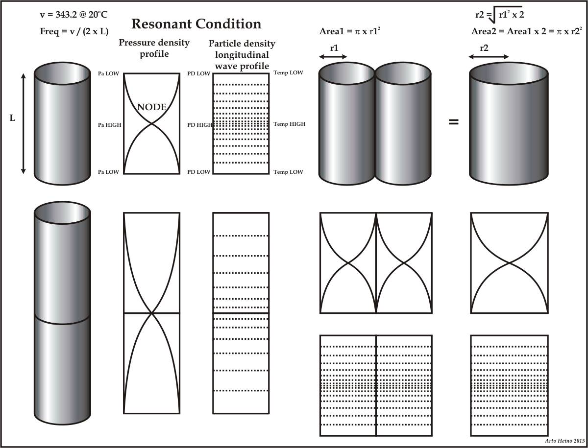
Audio frequency of tubes
– The resonant frequency decreases when two pipes are in series, where air current flow capability is the same and decreases due to greater frictional surface area
– The resonant frequency stays the same when two pipes are in parallel, where air current flow capability increases with the resistance also reduced as the volume increases greater than the resistive surface area.
In this case, the parallel system will develop a greater differential and an increase of air current volume, which could be translated into an volume flow transducers, thus moving energy out of the system by a translational device.
The parallel system uses a longitudinal pressure wave where the volume increase in the direction of flow and there is also resistance against the body of the tube which has greater increases in the serial version and is due to the surface area in contact with the vibrating air.
Pressure of water in tubes connected
– Pressure increases when two pipes are in series (elevation differential), where water current flow rate capability decreases and greater frictional surface area decreases the flow
– Pressure stays the same in parallel, where current flow capability increases
In this case, the parallel system will develop a smaller differential but an increase of water current volume, which could be translated into an volume flow transducers, thus moving energy out of the system by a translational device.
The parallel system uses a pressure bow where the volume increase in the direction of flow and there is also resistance against the body of the pipe which has greater increases in the serial version and is due to the greater surface area in contact with the water.

EMF of Batteries in Series and Parallel
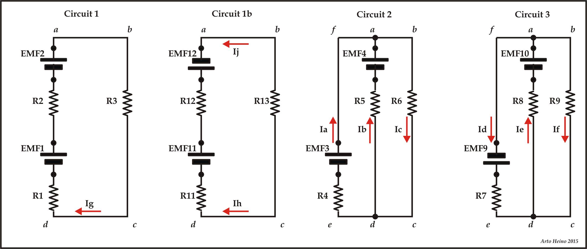
Circuit 1 – Batteries in Series
The current Ig through the resistance R3 in circuit 1
If
V = I x R
and
I = V / R
Then
V = EMF1 + EMF2 = I x R
When you have resistors in series you add the values together:
Thus
EMF1 + EMF2 = Ig x (R1 + R2 + R3)
Then
Ig = (EMF1 + EMF2) / (R1 + R2 + R3)
Example1:
If
R1 = 270 ohms
R2 = 230 ohms
R3 = 940 ohms
EMF1 = 12 volts
EMF2 = 3 volts
Therefore
Ig = (12 + 3) / (270+230+940) = 15 / 1440 = 0.0104166 Amps
Example2:
If
R1 = 2.7 ohms
R2 = 2.3 ohms
R3 = 9.4 ohms
EMF1 = 12 volts
EMF2 = 4 volts
Therefore
Ig = (12 + 4) / (2.7+2.3+7.5) = 16 / 12.5 = 1.28 Amps
Circuit 1b – Batteries in Parallel , End Load
Using Kirchoff’s Loop Rule
Where all possible loops that are valid can circulate
Loop 1 = b -> a -> x < -c <- d (This Loop is incomplete)
This is an unusual combination, even though EMF11 will become in equilibrium with EMF12, the actual load is a bridge conductor. This mean this load will in fact function but of a very small current differential.
Example 1a:
If
R11 = 3 ohm
R12 = 3 ohm
R13 = 8 ohm
EMF11 = 12 volts
EMF12 = 11.75 volts
Ih = R11 / EMF11
= 3 / 12
= 0.25
Ij = R12 / EMF12
= 3 / 11.75
= 0.255319
Thus the current in the load is
Iload = Ij – Ih
= 0.05319
by deduction we can also say
R13 = EMF13 / Iload
rearranging
EMF13 = R 13 x Iload
= 8 x 0.05319
= 0.04255 volts
This easily shows Kirchoff ‘s loop rule must also include the loops that arrive from two sources that are not the same, allowing a current to flow due to the nature of unequal equipotentials. This means we must first show the currents of each half loop then by subtraction leaving the differential, which should also be divided by 2 because the current will share the remainder with both current sources.
This also means that an additional Law must be applied to resolve this type of differential loop.
The Third Law – Only implies the incomplete differential loops.
Ij – Ih – ( EMF13/R13 ) = 0 Eq0
Circuit 2 – Batteries in Parallel
Using Kirchoff’s Loop Rule
Where all possible loops that are valid can circulate
Loop 1 = a -> d -> e -> f then back to a (This Loop is invalid)
Loop 2 = a -> b -> c -> d then back to a
Loop 3 = a -> b -> c -> d -> e -> f then back to a
The First Law
Ic – Ib – Ia = 0 Eq1
The Second Law
This implies to Loop2
EMF4 – ( R6 x Ic) – (R5 x Ib) = 0 Eq2
This implies to Loop3
EMF3 – ( R4 x Ia) – (R6 x Ic) = 0 Eq3
and rearranging Eq2
EMF4 – ( R6 x Ic) = (R5 x Ib) = EMF5
EMF4 – ( R5 x Ib) = (R6 x Ic) = EMF6
EMF4 = (R5 x Ib) + (R6 x Ic)
and rearranging Eq3
EMF3 – ( R4 x Ia) = (R6 x Ic) = EMF7
EMF3 – ( R6 x Ic) = (R4 x Ia) = EMF8
EMF3 = ( R4 x Ia) + (R6 x Ic)
Also rearranging Eq1
Ic = Ia + Ib
There are 2 current branches
if
Ia = EMF3 – EMF6 / R4
and
Ib = EMF4 – EMF6 / R4
Thus
Ic = (EMF3 – EMF6 / R4) + (EMF4 – EMF6) / R5)
To conclude
if
R5 = R4
then
EMF3 = EMF4
Then
Ic = (2 x EMF3 – 2 x EMF6) / R4
Then
Ic * R4 = 2 x EMF3 – 2 x EMF6
R4 = (2 x EMF3 – 2 x EMF6) / Ic
then
R4 = ((2 x EMF3)/ Ic) – (2 x R6)
(2 x EMF3)/Ic = R4 + 2 x R6
2 x EMF3 = Ic x (R4 + 2 x R6)
Ic = 2 x EMF3 / (R4 + 2 x R6)
and
Ic = 2 x EMF3 / (R4 + 2 x R6)
Also for the invalid loop1 we must use Eq1 to see what differential circulates between these 2 EMF’s, you will have to include another load R45 between R4 and R5 at e and d.
If using the 3rd law
Ia – Ib – ( EMF34/R45 ) = 0 Eq0
then
Iload = Ia – Ib
and
EMF34 = R45 x Iload
This can now be treated as an additional EMF depending on the direction of current, eg if Ia>Ib or Ib>Ia.
Example3:
EMF3 = 12 V
EMF4 = 9 V
R4 = 100 ohms
R5 = 50 ohms
R6 = 2500 ohms
Ia = 0.0213579 amps
Ib = – 0.0173684 amps
Ic = Ia + Ib = 0.0394737 amps Eq1
EMF4 – ( R6 x Ic) = (R5 x Ib) = EMF5
9 – (2500 x Ic) = 50 x Ib
rearrange then
Ib = (9 – (2500 x Ic)) / 50
Also if
EMF4 = (R5 x Ib) + (R6 x Ic)
= (50 x Ib) + (2500 x Ic)
= 9 volts
EMF4 – ( R5 x Ib) = (R6 x Ic) = EMF6
9 – (50 x Ib) = 2500 x Ic
Rearrange then
Ic = (9 – (50 x Ib)) / 2500
then by Eq1
Ia + Ib = (9 – (50 x Ib)) / 2500
Rearrange then
Ia = (9 – (50 x Ib)) / 2500) – Ib
and rearranging Eq3
EMF3 – ( R4 x Ia) = (R6 x Ic) = EMF7
12 – (100 x Ia) = 2500 x Ic
Rearrange then
Ic = (12 – (100 x Ia)) / 2500
then by Eq1
Ia + Ib = (12 – (100 x Ia)) / 2500
Rearrange then
Ib = (12 – (100 x Ia)) / 2500) – Ia
EMF3 – ( R6 x Ic) = (R4 x Ia) = EMF8
12 – (2500 x Ic) = 100 x Ia
Rearrange then
Ia = (12 – (2500 x Ic)) / 100
then by Eq1
Ic – Ib = (12 – (2500 x Ic)) / 100
Rearrange then
Ib = -1 x ((12 – (2500 x Ic)) / 100) – Ic)
Also if
EMF3 = ( R4 x Ia) + (R6 x Ic)
= (100 x Ia) +(2500 x Ic)
= 12 volts
The power dissipated by R3 for circuit 1
Example4:
if
EMF1 = 12 V
EMF2 = 12 V
R1 = 100 ohms
R2 = 50 ohms
R3 = 2500 ohms
and if Power is Pa
Pa = I^2 x R
and I is
Ia = (EMF1 + EMF2) / (R1 + R2 + R3)
= 0.0090566
So
Pa = [(EMF1 + EMF2) / (R1 + R2 + R3)]^2 x R3
The power dissipated of R3 using values
Solution:
Pa = [(EMF1 + EMF2) / (R1 + R2 + R3]^2 x R2
= [( 12 + 12 ) / (100 + 50 + 2500)]^2 * 2500
= [24 / 2650]^2 * 2500
= 0.205
Example5:
If
EMF1 = 12 V
EMF2 = 12 V
R1 = 100 ohms
R2 = 100 ohms
R3 = 200 ohms
R4 = 200 ohms
R5 = 200 ohms
R6 = 200 ohms
For what ratio of R1 and R2 would power dissipated by the resistor of resistance R2 be the same for circuit A and circuit B?
As long as the voltage and current are the same, the power will be the same if the resistors are equal. So the answer is, so long as:
If
EMF1 = EMF2 = EMF3 = EMF4
and
(R1 + R2) / R3 = 1 Eq4
[(R4 x R5)/( R4 + R5)]/ R6 = 1 Eq5
Circuit 3 – Batteries in Series and Parallel
Using Kirchoff’s Loop Rule
Where all possible loops that are valid and can circulate
Loop 1 = a -> d -> e -> f then back to a
Loop 2 = a -> b -> c -> d then back to a
Loop 3 = a -> b -> c -> d -> e -> f then back to a
The First Law
Id – Ie – If = 0 Eq6 4
The Second Law
This implies to Loop1
EMF9 – EMF10 – ( R8 x Ie) – (R7 x Id) = 0 Eq7 5
This implies to Loop2
EMF10 – ( R9 x If) – (R8 x Ie) = 0 Eq8 6
This implies to Loop3
EMF9 – ( R9 x If) – (R7 x Id) = 0 Eq9 7
When 2 batteries are put in parallel they will try to equalize the total charge that is available, thus a 11v connected to a 13v theoretically should equalize to 12v. This is the technology of of Ron Brant and others, where battery switching technology is not a mysterious or esoteric topic in engineering as it may seem, but due its uncommon applications it has developed in to a wild “free energy from the vacuum” cult following. This has happened over a 30 year period, saying this, it is still an interesting and unexplored territory and should be given some credence to evaluate possible parametric additions to the flow rate between these cells. This is where Kirchoffs invalid current loops become valid which now can be translated to include another branch that can be added from an outside environmental circuit, regardless if the basic layout are completely valid, thus giving a perfectly reasonable validation for external energy coupling. The anomalous readings that the researchers sometimes encounters when making experimental circuits can easily be included as differential current movements, this sometimes happens in some simple circuits when the environment has EMF leakage currents that circulate from power systems, through bad earths or inductive couplings when metal components contain eddy currents.
So when Tesla made his simple and accurate discovery that “all energy is received from the external environment”, it becomes validated once again. Thanks for reading regards Arto.