Posts Tagged ‘science’

Saqqara Ostrakon

December 5, 2012

SAq1

Saqqara Ostrakon a Different and Exact Solution

by Arto Heino 2012

Having solved many numeric puzzles using Quantum Arithmetic, I decided to attack this interesting artifact with relish. It seems everybody had a go at this including Graham Hancock. I am glad to express my delight in the solution that I have found, revealing the true principles of Ancient Khemitian(Egyptian) geometry and part of the foundation of building and pyramid design and the reason for their construction principles. As I will show on a another blog entry, I have found one of the the final keys to knowledge of the ancient Pyramidic geometric cipher, no weird magic number or symbol required, this is truly exciting and I will notify all interested parties when my blog is published.

The Saqqra OstraKon was found at the excavations in Saqqara in 1925, the writing reveals this object has a geometric value. The inscription is a form of shorthand to a larger idea.

3 Cubits, 3 Palms, 2 Fingers = 98 Fingers = 1837.5  mm
3 Cubits, 2 Palms, 3 Fingers = 95 Fingers = 1781.25 mm
3 Cubits, 0 Palms, 0 Fingers = 84 Fingers = 1575    mm
2 Cubits, 3 Palms, 0 Fingers = 68 Fingers = 1275    mm
1 Cubit , 3 Palms, 1 Finger  = 41 Fingers = 768.5   mm

1 Cubit  = 7 Palms = 28 Fingers = 525 mm (using this conversion size in millimeters)
1 Palm   = 4  Fingers = 75  mm
I Finger = 18.75 mm

The small curved line and a few strokes and the numbers above is all that was needed. The 98 Fingers was the first clue, this would be the Perihelion or in QA the J factor. The plane number 98 didn’t fit with any Quantum Ellipse so a multiplication or conversion number must have been used, after a few attempts it looks like the prime number 5 was the cipher.

G _ H  = 490 = 5 x 98
N _ W  = 475 = 5 x 95
D _ Z  = 420 = 5 x 84
R _ B1 = 340 = 5 x 68
T _ C1 = 205 = 5 x 41

Now that I know J= 98 then as in all QA you can work backwoods to find the roots of the ellipse. These are the original root numbers that I found:

b = 2    e = 3  d = 5   a = 8  , these will give you J = 10 and the eccentricity of 0.6

b = 14   e 21   d = 35  a = 56 , these will give you J = 490 and the eccentricity of 0.6

The prime factor underlying the x 7 is a way of finding the other derived numbers in a simple translation as J=98 is not a Quantum root size it is a derivation from a physical measuring system from a Quantum number set.  This diagram should explain the geometry.SaqqaraElli4

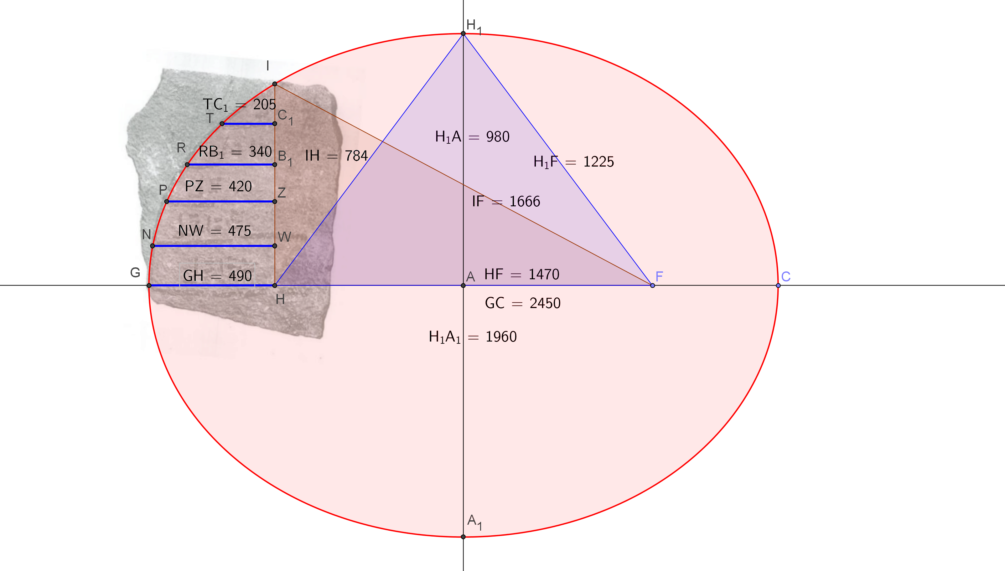
The reason I exclaimed the true solution is because of the following hidden variables. The redrawn diagram everybody followed by Battiscombe Gunn is incorrect, looks like his pet theory of 28 fingers between lines was wrong, as you can see by the original carving the lines are not evenly spaced, it was only a crude diagram drawn without a rule, you cannot base the intention of the geometer on a rough sketch,  only on the description he gives and the approximate position of all the lines. All QA requires is some real numbers and an approximate shape to define the correct form.

These are exact values with no decimal fractions:

H _ W  = sqrt(  23376 )
H _ Z  = sqrt( 106624 )
H _ B1 = sqrt( 220800 )
H _ C1 = sqrt( 394896 )
H _ I  = Sqrt( 614656 )

These are the values when J=490, they reveal the correctness of the QA precision  You will never arrive at this sort of numeric clarity using any mathematical tricks, the Quantum Ellipse is a unperturbed form and non empirical.  The values when J=98 re listed below:

H _ W  = sqrt(   935.04 )
H _ Z  = sqrt(  4264.96 )
H _ B1 = sqrt(  8832    )
H _ C1 = sqrt( 15795.84 )
H _ I  = sqrt( 24586.24 )

What we are looking for is the gap sizes, here is J=490

H _ W  = sqrt(  23376 )
W _ Z  = sqrt( 106624 ) – sqrt(  23376 )
Z _ B1 = sqrt( 220800 ) – sqrt( 106624 )
B1_ C1 = sqrt( 394896 ) – sqrt( 220800 )
C1_ I  = Sqrt( 614656 ) – sqrt( 394896 )

Here are the final values decoded and back to empirical finger and metric measure

H _ W  = sqrt(  935.04 )                                    = 30.5784237 Fingers = 573.3454456 mm
W _ Z  = sqrt( 4264.96 ) – sqrt(  935.04 )  = 34.7282374 Fingers = 651.1544523 mm
Z _ B1 = sqrt( 8832    ) – sqrt( 4264.96 )    = 28.6720597 Fingers = 537.6011207 mm
B1_ C1 = sqrt(15795.84 ) – sqrt( 8832    )  = 31.7027812 Fingers = 594.4271479 mm
C1_ I  = Sqrt(24586.24 ) – sqrt(15795.84 )  = 31.1184877 Fingers = 583.4718333 mm

These sizes were not needed by the Khemitian geometer to their requirements only the right angle edge and the curve was needed, only modern calculus require these values as to plot X * Y curves. The Khemitians had no need of such crude mathematical devices such as calculus, they treated the curve as a different type of measure than the straight line. Now we can extrapolate the Cubit/Finger and metric size of the whole ellipse.

Length of the ellipse is = 2450 = 490 x 5 in Fingers = 490 = 17 Cubits 3 Palms 2 Fingers = 9.1875 mtrs

Width of the ellipse is = 1960 = 392 x 5 in Fingers = 392 =  14 Cubits = 7.35 Mtrs

The values are correct as no extra bit of a finger is required, this one of the reasons the Khemitians used these types of measure. The translation into quantum units were simple and there were no fudge factors that required PI, PHI or Log, no fractional decimals, only whole numbers  So the final outcome underlies how truly powerful Quantum Arithmetic is when fully understood and utilized in the right hands, when looking for a accurate solution without errors from empirical measurements and data from approximation using calculus.

These and many more are from my up and coming book “Talking to the Birds”, regards Arto

References
An article by Battiscombe Gunn
Published in Annales du Service des Antiquites de L’Egypte,
Volume 26, 1926, pages 197 – 202
Printed by the Institute of France, Oriental Archaeology,
Le Caire, France

Diagram was created by Arto Heino using GeoGebra

*** New Addition *** 2021

I can see some are not convinced of my odd methodology, here is ample proof that simplicity was the key.

As the diagram illustrates:
IH = 784
HF = 1470
IF = 1666

Add together to create the perimeter of the triangle, thus:
784+1470+1666 = 3920

Now return back to Finger measure:
3920 / 5 = 784

Now return back to Royal Cubits:
784/28 = 28

Thus if you have a string 28 RC long and joint it to make a loop, then you make two pegs on the ground at the distance of:
1470/5 = 294 fingers = 10 RC + 14 F

You can now trace this ellipse with a marker at a third point when you stretch the string. Refer to the diagram below using the 3-4-5 triangle giving 12 as the perimeter.

I hope that simplifies my reasoning why I use QA to solve these ancient problems. Regards Arto

Quantum Arithmetic

November 22, 2012

This is another brief expert from my book “Talking to the Birds”, I hope you enjoy it. I have included some notes from Ben Iverson as well.

Only a trained mathematician/geometer can recognize the missing elements in the geometric canon, that which has been ignored for the last 60 years, you cannot accidentally or casually find this most unique arithmetic, it is not based just on porisms. It is not number theory or invented mathematics, it does not need calculus, there is no approximations, it does begin its understanding as the trivial terms that most assume to be understood. Let us begin with the trivial terms so we can dispense with all the mystery.

Quantum Arithmetic uses a natural number system which has a base in of all of the prime numbers which occur in the problem you need to solve. All its numbers are interlocked in a geometric arrangement. All numbers are positive integers, no decimal points or irrational numbers. Addition, subtraction, multiplication and division is all that is mainly required, the use of square roots and diadic fractions are also used, they are mainly used to verify the results and find the whole number ratio’s. The ordering into Par numbers can also verify and help understand the internal arrangements.

There are sixteen primary identities. The first four are given the identity of “a”, “b” “e” and “d”. These, are the roots of its given problem, and is the base numbers. The next twelve identities are the upper case letters A through L. They are combinations, of the first four base numbers, and are usually considered as one dimension, higher than the base identities. They will denote linear dimension, surface areas, or volumes, for the three standard dimensions above the roots.

There is also one dimension below the “roots” b, e, d, and a. They are called “quaternions”, and are the square roots of the root numbers. In conventional mathematics, these are called “Gaussian Integers”. They are integers, only when their base number is a perfect square. A problem in QA is well defined and problems solvable when only one of the upper case identities is assigned a value and the name of that identity. All of the values within a problem in QA are intertwined this gives you hundreds of ways to solve any given problem.

The Quantum Number for one figure is the same for all geometric figures. A single quantum number defines the magnitude of the measurements, as they are related between themselves. Different geometric figures can be connected and their dimensions are calculated once for all of the various shapes. The shapes used are:

1 Right triangles

2 Equilateral triangle

3 Isosceles Triangles

4 Triplet circles (Koenig Series)

5 Triplet Squares (Koenig Series)

6 Ellipses

Each shape is calculated from a single Quantum Number. The one requirement is that the second and third integers of the Quantum Number must be prime to each other. These are in the Fibonacci sequence. They derive from Euclid VII, Proposition 28. The first and fourth integers become, “Sum and Difference” numbers.

All Quantum ellipses will give the value one when you apply the Steiner Inellispe porism. The numeric laws it contain can be geometrically reconstructed with s0me of the most excellent programs such as GeoGebra, First you need to understand the construction of the “Quantum Ellipse”. The usual 2 foci and semi-major length/third point will not suffice only Conic section ellipse will create the correct elliptical form, if you have 5 points that are aligned to the quantum arithmetic standard. I hope some of these diagrams will help clarify all the parameters. The best way to construct an ellipse of this sort is to start with a string with length 3+4+5=12 a Pythagorean triangle. This method was re-discovered by James Clerk Maxwell in the mid 1800’s.

This type of geometry had been developed by Ben Iverson from the 1950’s through to to 1990’s extended by Dale Pond and myself over the last 20 years.

After many calculations and with the application of Quantum Arithmetic, I have created a beginning for the foundation of the Quantum 120degree Isoceles. The smallest integer units begin at the 4 digit root numbers, which means some calculations are up to 20 numbers long This study has revealed the Quantum Equilateral also within its perimeter, having now multiple Z line integers.

Listed below is the some of the raw data for one of the smallest Quantum Isosceles 120 degree Triangle, the added Var1,Var2,Var3,Var4,Var5,Var6 are part of an incomplete data list, you can ignore them or just make each equal zero.

b = 2646 = d – e

e = 4343 = a – d

d = 6989 = b + e

a = 11332 = d + a

B = 7001316 = b x b

E = 18861649 = e x e

D = 48846121 = d x d

A = 128414224 = a x a

C = 60706454 = 2 x d x e

Fe = 29984472 = d x d – e x e + Var1

G = 67707770 = d x d + e x e

L = 151687580848524 = ( d x d x d x e – e x e x e x d ) / 6

H = 90690926 = ( a x a + 2 x b x a – a x a ) / 2

I = 30721982 = ( e x e + 2 x d x e ) – d x d

J = 18492894 = d x d – d x e

K = 79199348 = d x d + d x e

We = 109552575 = d x e + d x a

X = 30353227 = d x e

Ye = 79568103 = 2 x d x e + d x d + Var2

Ze = 98060997 = e x e + d x d + d x e + Var3

Wib = 328657725 = 3 x ( d x e + d x a )

Fi = 109552575 = d x e + d x a + Var4

Yi = 219105150 = 2 x ( d x e + d x a ) + Var5

Zi = 109552575 = d x e + d x a + Var6

Wis = 189750626 = ( d x e + d x a ) x sq 3

Wh = 94875313 = ( ( d x e + d x a ) / 2 ) x sq 3

Thank you

Regards Arto


The Nested Magic Square of 15

November 1, 2012

This is a small addition to my blog from one of the pages in my book. This is one of my early(1996) investigations into different interpretations of the magic square sequences. This led me to redefine particular geometries that could be  understood in terms of the changes in dynamics that can create rotational causality, such as imbalanced wheels etc. The placement of the sequential string of numbers towards the center, offsetting one number after two turns and on the third creating a completed section before returning back to the first compliments a vortex action that can been seen not just imagined, actually 4 vortices. I am including this here so to further the understanding of a new way of to interpret the magic squares, numbers patterns that has always existed and never created by man.  Regards Arto

Contra-Cyclic Harmonic Archimedean Geometry

October 5, 2012

Here are some of the files I have released in the Energetic Forum recently. In them I am dealing with a geometry that has been used in many types of machines for thousands of years ranging from Archimedes all the way to Da Vinci, Huygens,  Bessler,  Keely, Russel, Constantinesco and to all the late 19th century mechanical inventions and now to the whole free energy fraternity that seem to think these things have not been discovered before or even understood by previous generations. I am a wittiness to a unique renaissance in this type of research as seen by a multitude of patents, designs and inventions  in torque conversions and unique mechanical advantage systems.These reveal the simple but hidden aspects of geometry, as I have seen by perusing hundreds of patents and engineering catalogues,  still I find nothing historically new but a creatively variant and diverse  application of a multitude of designs, utilizing a hidden pallet that engineers need to know about and define as a branch of dynamic geometry.

Nicola Tesla hinted at the electrical version of this higher geometric typology, most of his inventions had this at its center, where logarithmic curves are not approximated and linearized. The etheric geometric relationships of these phenomena has been elucidated by Eric Dollard in his many publications, videos and writing, showing a precise 4 quadrant nature to electrical phenomena, no Einstein or Maxwell misunderstandings and disinformation required here . What is the core of this version of science, engineering and understanding?, it is ancient geometry of course, or as some call “Sacred Geometry”, the same as ALL the crop circles around the world. The geometry of Archimedes, toroids, pendulums, spherical geometry, Huygens Evolutes and Caustics, Bruce Cathie,  versins, haversins, Quantum Arithmetic(as per Ben Iverson, Not Quantum Physics)  and  Great Pyramid geometry could all be involved. The new branch would be viewed as 3d dynamics that cover those geometries of spherically rotating pendulum, single,  double and triple stages with optional locations of pivoting axis, that could be called an upside down rotating spherical pendulum.

The machine designed by Sixto Ramos reveals this type of geometry very clearly, it relates to the Archimedean twin circle(fibonacci/golden) geometry, as you can see toroidal geometry is also involved. Looking at the forms created in its action you can see a part of the conchoid of de Sluze family of curves.

As you can see I have added an extra pointer in the geometry that relates to the great pyramid. This I will carry through to the Ucros device.

George Constantinesco must be included in this array as his devices are the most elegantly designed and understandable from all the types of these torque converters you will ever see.

To conclude these machines , I have a design that uses the hyperbolic curve as the geometric element in the design, accomplishing the similar results as the Sixto design.

Here is a geometric diagram that includes the Archimedean twin circles and the basic geometry of the Ramos machine  I hope this will help in understanding some of the ideas shown here.

I would love to include the section relating to Veljko Milkovic as his inventions has gravitation as the other inlaid geometry. Some of these diagrams and graphics here are included in one of my chapters in my book “Talking with the Birds” Vol I & II. **note** Volume I of my book is now available at Amazon.com, please check here.


The Adams Motor

September 13, 2012

In 1986 I was designing some unique colour-music art (Synesthesia) and looking at ways to put this into electronics using leds, lasers, cathode ray tubes or computer programs, this led me to designing a colour organ that was fully integrated with audio correlation to the harmonic contents of the sound as well. I decided to apply for a patent and went to the patent office to do a search for similar devices.

During the search I listed a few names and previous attempts, which went all the way back to 1890’s, while I was their I also looked for new developments in electric motors, this was the moment I found the Adams motor and noted the inventor was from New Zealand and he had patented his invention in 1969. I immediately concluded this simple design would be very efficient and unique as all the poles were of the same polarity, this was duly noted and I pressed on with other matters at the patent office. Amazingly enough I did end up the the Edison Electric offices where I explained the basic tenants and principles of this colour-organ to a few very attentive engineers.  Later in that month I met with one of the patent holders for one of the colour-organs who just happen to be an artist as well and lived in Sydney.  Before the month was out I wrote to the Sharp corporation and presented my findings and possible applications on my invention, they wrote back to me with a generous tone and kept me in mind for any future developments in this direction.

A brief description of my colour organ – Frequency correlated harmonic fourier separation to colour chroma addition translated to voltage steps controlling electron charge amplifiers  creating a proportional light intensity and equated colour area and location in the visual field, the resultant beam or electric display (Tesla coils with or without  gas enveloped top loads, closed electron tube/ phosphor display, optical wall/3D display, Holographic multi- projectors, laser projectors) would modulate with sensitive modes that equated to the overall mood and flowing structure of the music based on translating electronics. Some of these ideas have been used by others in recent years, due to the advent of readily available electronic component modules.

This chance study of the Adams motor at the patent office was originally prompted by a childhood dream of a free running motor that collected the energy from the universe to power it. This reoccurring dream was in the late 60’s when I was building crystal radio’s, high voltage coils, transistor circuits and single valve circuits.  This was the time I listened to Short and Long wave radio with my home made aerials picking up whistlers and other radio noise that I found by pointing my wire dishes at different portions of the sky and at different times of the day and night. I was about 12 at the time when a lot of these ideas about how these things operated occurred to me.

In early 1990’s I started compiling my various work on many subjects including motor design, when I was pleasantly surprised that Robert Adams published a ground breaking article in the Nexus magazine on his motor design. This was an exiting time as a lot of the backyard and professional engineers were collaborating and working on many new devices. At this time in Sydney there were group meetings and we were showing our current builds and exchanging information between members, the only problem was the new paradigm of over-unity engineering was not developed enough to handle the questions many members had. As always, I was the outsider who didn’t put faith in the current techno-babble of electrical engineering, being self taught in these matters, I relied on basic tenants of creating the equations from the evidence, not forcing the build to comply with the equations. This is what I gleaned from most of  the Scientists and Inventors of history mainly  Leonardo Da Vinci, Nicola Tesla and Victor Schauberger. In a desperate attempt to help my fellow builders I met with Robert Adams at the Sydney Nexus conference, from that moment on I  corresponded with Mr Adams a few times and sent him a few of my design sketches. I will include a copy of one of the letters I received from him, below.

Letter from Robert Adams to Arto Heino

The testing process of my build of the Adams motor was arduous and drawn out over a least 2-3 years, I had to learn many new skills and I developed an intuitive insight into this simple motor that goes beyond equations and engineering. The great help came from the generous group I was involved with at the time, I was loaned a oscilloscope, that is when the next phase of my journey began. I tried to convey the results to my fellow researchers and found they were closed minded about developing new equations that included open systems, I met with many and explained the tenants of true free energy, they turned to their university books and denounced anything that was not written in the science bibles. As I was not brainwashed in these matters, I could see their distress when I confronted their most hallowed beliefs of the system of modern science they were taught as sacrosanct, alas Einstein ruled. I am not a scientist or an engineer, I am an Artist from the school(mind set) of  Leonardo da Vinci and Walter Russel , therefore I am a natural scientist and observer of phenomenon, please allow me at least this modesty for my years of study and practical application .

I moved away from trying to convince others of the errors hidden in the equations and I allowed the natural curiosity and time for them to realize and discover it in there own time, the greatest teacher is ones own experience. This has been the legacy of Robert Adams, a man who spent a lifetime serving the system only to confront it head-on with its own  fallacies. Robert had been attacked on many occasions by the agents of a flawed science, only to be praised by those who have already awakened to the same dilemma  such as the notable scientist Harold Aspen. Their written legacy still exists for other to learn from.

I will not include in this blog the 400 odd tests that I performed as this would prove nothing, the tests were for me to understand the operations of the motor circuitry and look for environmental correlations. I have seen many people approach the design of the Adams motor with a sledge hammer, with stronger magnets, faster speeds, larger disks, bigger coils etc, this has always been to no avail as the basic understanding has been missed. This motor will run in a resonant fashion, to itself and the environment. This is the key, do not underestimate what Robert Adams tried to convey with his descriptions and explanations. Look at the  wave functions  of the whole solar system, day/night,  altitude,  atmospherics, terrulian currents, temperature, EM fog and geographic location before you make conclusions about how this simple motor operates. Energy is everywhere, tapping into this resource takes patience, observation, curiosity, creativity and sound scientific principles. Do not be led into a blind alley of dogmatic procedures that  avoid the hidden truth that we live in an OPEN system and energy is always available to be used through the correct gating mechanisms that we discover.

Here is a schematic of the Adams motor design as I have come to understand, I have not included all the equations required to build such a motor/gen, just the basic schematic I have revealed. The complete transcriptions and equations will be in my book “Talking to the Birds”, Regards Arto

The Adams Motor

The Adams Motor


Multi-Filar Coils

August 24, 2012

While making observations of coil designs that have been used over the centuries, I noticed only those that showed some perceived useful results were kept in the arsenal of the scientists, the rest were either ignored or forgotten. There are two basic types and a 3rd being the combination:

1 Circular – Eg Solenoid, flat spiral,spherical, toroidal, mobius

2 Non-circular – Eg Basket weave, geometric, polyhedral, star forms, mobius

The circular types have 3 basic types  a resultant 4th and the unique 5th type:

1 Rings adding vertically –  Solenoid Coil

2 Rings expanding diametrically  – Flat spiral

3 Rings adding in a circular form – Toroidal

4 Rings adding vertically and/or diametrically and/or circular

a) Conical – differing sizes in both direction

b) Multilayer Solenoid – same sizes vertically + differing sizes diametrically

c) Multilayer Flat Spiral – same coils sizes vertically + adding vertically

d) Toroidal and Poloidal windings mixed sizes vertically + differing sizes diametrically

e) Spherical rotations windings mixed sizes radially + differing sizes diametrically

5 Winding folding into itself, creating a single surface  – all possible geometries – Mobuis

The shapes of coils are one aspect the other is the winding order and direction, thus creating multiple poles, cross coupling inductance, retarding or increasing both the inductance and the capacitance as the design requires, the addition of the mobius windings diversifies the basic options, this is where the art is at in 2012. A good example of combining many geometries and winding types is the:

Magnetic coil(1820 Hans Christian Oersted)

Faraday coil(1831 Micheal Faraday)

Henry coil(1831 Joesph Henry)

Induction coil(1836 Nickolas Callan)

Ruhmkorff coil(1851 Heinrich Ruhmkorff)

Helmholtz coil(1869 Herman von Helmholtz)

Maxwell coil(1873 James Maxwell)

Cook coil(1871 Daniel Cook)

Tesla coil 1/4 wave(1891 Nicola Tesla)

Tesla Flat coil(1890 Nicola Tesla)

Tesla Bifilar coil(1894 Nicola Tesla)

Hubbard coil(1918 Alfred Hubbard)

O’Leary Coil(1920 William O’Leary)

Hendershot coil(1928 Lester Hendershot)

Interceptor coil(1946 John Wiegand)

Tokamak coil(1950 Oleg Lavrentiev)

Stellartator coil(1950 Lyman Spitzer)

Smith coil(1952 Wilber Smith)

Fusor coil(1964 Philo Farnsworth)

Hooper coil(1968 William Hooper)

Rodin coil(1986 Marco Rodin)

Biaxial Poloid coil(1990 Bo Atkinson)

Tetra Helix coil(1991 Bo Atkinson)

Vortex coil(1992 Ken Gailey)

Double Helix coil(TM) (2007 AML)

Not to mention my own explorations in coil geometry with:

Mandela coil(1990 Arto Heino) – Page 55 – Link

Crown coil(1994/2011 Arto Heino) – Link

Infinty coil(1993/2011 Arto Heino) – Link

– and many toroidal/polyhedral mixtures that have been popping up regularly with names like the Star ship coil, Loohan coil, Polish coil,  Big Secret coil, some of these are marvels of artistry and human innovation.

Not to mention the many non inductive windings that are used as resistances. This has been looked at for at least 200 years, Nicola Tesla was one engineer/Scientist who’s original thinking left a legacy of numerous winding geometries he used to design his motors and coils,one of these is his Bifilar design. This design exposed a unique addition to the idea of combining the merits of both coil and capacitor without addition hardware contrivances, the anti-series winding nulls out self-inductance.

Nicola Tesla writes that a standard coil of 1000 turns with a potential of 100 volts across it will have a difference of 0.1 volt between turns.
100/1000 = 0.1
A similar bifilar coil will have a potential of 50 volts between turns.
100/2 = 50
In that the stored energy is a function of the square of the voltages, the ratio of energy in the bifilar to a standard coil will be
50^2/0.1^2 = 2500/0.01 = 250000
Which as stated by Tesla, “the energy stored is 250000 times greater than the standard coil!”

The storage of energy when pulsing a bifilar coil is n amount more than a standard solenoid/flat coil, as Tesla stated and gave you the formula to engineer this type of coil, we should be incorporating this simple idea into many everyday devices. I have drawn a few design methodologies that I hope will spur this well known innovation into more interesting directions.

These are basic bifilar solenoid configuration showing the capacitance between each winding. The windings can be rearranged in a different order to change the amount of induction and capacitance you put into the coil.  The winding below shows what can be done to rearrange the capacitive differential to increase the energy storage.

The graphic table below shows how many different arrangements that can be used with a Quadrifilar coil system, each will give a different result for the inductance, capacitance and its resonant frequency spectrum.

A great science/engineering project or University paper for someone would be to tabulate and analyze  each arrangement,  you might just get your doctorate on this.

The flat coil is a dimension less than the solenoid and a lot easier to redefine into  multi-filar arrangements.

The basic geometries involved in designing coils, transformers and bifilar systems must have a few design rules so the engineering of these items become straight forward and adaptable to the needs of the energy transformations. Here are a few simple systems that can be easily expanded and used creatively.

The cipher I am using here is:

B = Blue              R = Red

U = Upper          L = Lower

N = North           S = South      / is the upper part of the cross

E = East               W = West       \ is the upper part of the cross

The order of the letters is the order from the top to the bottom.

The order of the numbers is from the left to the right.

The first set is based on 2 simple loops. This will give you 8 different forms:

The next is the topology of a single loop of wire which loops on itself, like a bifilar or just a plain solenoid:

As you can see by these configurations, the standard engineering practice used in industry only use a small portion of these geometries. Now if you loop 2 coils as used in transformers you will see industry only apply 1 or 2 of these geometries in 98% of all transformers.

The fusing of  Adams motor and the Tesla bifilar coil was one of the first iterations that showed me the correctness of this approach by its exceptional efficiency.

Incorporating both bifilar and loop transformations as shown previously, you can begin to appreciate the transformations I have below to create a magic square coil, as originally shown on my Artoworld website in 1999.

Old photo from 1999

Most of the original readers of these documents never understood my topology in 1999, even though I built many of these coil constructs as stators for pulsed motors. The current breed of experimenter has less inhibitions to these  geometric forms. The first arrangement is the non-magic numeric sequence, just the same as if you wrap a standard solenoid.

Colimag4

The next diagram is the magic square arrangement, which utilizes the the pairing of the “17” as a magic square paring which translates to the bifilar pairing.

Below is the original stator coil I wound in 1999, it performed well and required high voltage(24v) and low current(0.001 amp).

I hope this small extract from my upcoming book “Talking with the Birds” will be helpful in any research you might be doing. Regards Arto

Here is  Link to a Multifilar Coil Manufacturer, called Custom Wire Technologies Inc. Give them a buzz they might help you, Regards Arto

https://customwiretech.com/

*** Update***

I have had a request to explain the Tesla/Adams Bifilar setup, here is a diagram that should make it transparent. The consequence of using this way of connecting coils will give you a multitude of possibilities for the experimenter to find interesting combinations ,  have fun regards Arto.

AdamsCoilsb2*** Update 2 *** 03-06-2013

Thanks to Andy I have added one more diagram to help decipher my Magic Square Coil arrangements.

AdamsCoilsc3

*** Update ***

Added the Spiral coil implementation.

AdamsCoilsd4For the continuation of this blog go to : https://artojh.wordpress.com/2013/06/05/magic-square-coil-technology/

Or buy my book at Amazon.com

One-Time
Monthly
Yearly

If you would like to help my efforts in all my future posts, I would very much appreciate your donation.

Make a monthly donation

Make a yearly donation

Choose an amount

¤5.00
¤15.00
¤100.00
¤5.00
¤15.00
¤100.00
¤5.00
¤15.00
¤100.00

Or enter a custom amount

¤

Your contribution is appreciated.

Your contribution is appreciated.

Your contribution is appreciated.

DonateDonate monthlyDonate yearly

The Infinity Coil

August 4, 2012

When I was working on the many forms of the Robert Adams motor in the 1990’s , I was happy to fulfill the basic tenants of the original Robert Adams design. The clear revelations of a simple switched reluctance motor with parametric amplification factors that can go into resonance with itself and the larger environment gave me inspiration in the form of a double coil in the figure eight with two rotors running in opposite directions and two sets of pulse coils.

After many years I decided to return back to these designs as they merit greater experimentation. The original Infinity coils were two solenoids in parallel wound in a figure eight fashion, this would also work on two toroids stacked in parallel also adding the bifilar winding scheme, this became my final design as shown below.

As to the functionality of this coil, I put together a simple pulse circuit, that only uses a 0.5-3volt source and lights a MR16 3W light for about 10 hours beginning at 60% illumination, as shown below.

There is still more work that has been done on this arrangement as all relevant factors are notated in my up coming book ( “Talking with the Birds”) and have been explored to a greater degree than presented here. Regards Arto