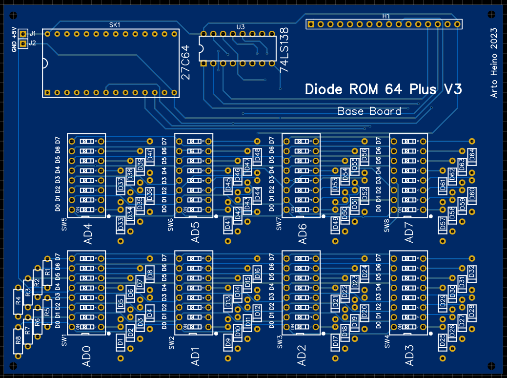
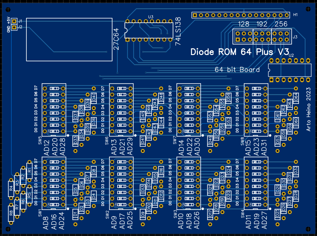
As my research moves along, I decided to create a Diode Memory unit first for binary use, before I implement the ternary memory version. I designed 2 types of boards, the first is the base board which is the first 64 bits or 8 bytes, the 2nd board can be stacked on top to create 128 bits or 16 bytes with more boards on top for 192/256 bits or 24/32 bytes. I will be building these soon, as these designs have not been tested yet, I suggest checking my work, I will confirm these in another blog.

The ROM choice was a 27C64 which is a 8Kx8 and is very popular, available in general stock and I will use it in further designs, the decoder is a 74LS138 which seems to be a great choice for this simple project. The only problem I had was the 138 has only 3 bits to decode, so I had to add a few extra bit of routing to create 32 bytes. The 138 has 3 enable lines GA_, GB_, G1, so the first block I put G1 high and GA_and GB_ would be enabled when both are low, these are from the A3 and A4 lines which are low. The second block I put GA_ low to ground with GB_ and G1 would be A4 as low and A3 as high. As you can see by the diagram I swapped A3 and A4 with GA grounded for the 3rd block, the last block I used an inverter on GB_ from A3 which must be high,
If you are not using 32 bytes then you can ignore the 74LS04 connection. To use each block you must bridge the labelled connectors with jumpers. The Parts list for 2 boards are:
SK1 = 28 pin DIP socket with extended legs
H1 = 16 Pin socket with extended legs x 2
U3 = 74LS138 x 2
R1-R8 = 10K resistors x 2
D1-D64 = 1N4148 Diodes x 2
SW1-SW8 = 8 sw DIP x 2
J1-J2 = Pin for Power x 2
Each corner has 2mm holes , add crews and extended legs as needed x 2
If you choose to build it, you will be limited to 32 bytes. To test the unit you could plug it into to a EPROM reader. My next version should allow up to 256 bytes or more. Regards Arto.


Diode ROM PCB1C Zipfile
All the PCB and Schematics for this project. EasyEDA files only.
$15.00
